
Differential braking of aircraft landing gear wheels

a technology of aircraft landing gear and differential braking, which is applied in the direction of aircraft braking arrangements, brake regulators, braking systems, etc., to achieve the effect of reducing the amount of braking applied, limiting and reducing the risk of aircraft damag

Active Publication Date: 2017-11-07
AIRBUS OPERATIONS LTD +1
View PDF16 Cites 3 Cited by
  • Summary
  • Abstract
  • Description
  • Claims
  • Application Information

AI Technical Summary

Benefits of technology

The invention aims to reduce the amount of braking applied to the wheels of an aircraft while still maintaining the desired braking parameters. This reduces the risk of damage to the aircraft and allows for any desired differential braking to still be applied.

Problems solved by technology

A problem with the automatic braking function of U.S. Pat. No. 4,646,242 is that it makes no provision for differential braking.

Method used


Image

  • Differential braking of aircraft landing gear wheels
  • Differential braking of aircraft landing gear wheels
  • Differential braking of aircraft landing gear wheels

Examples


Embodiment Construction

)

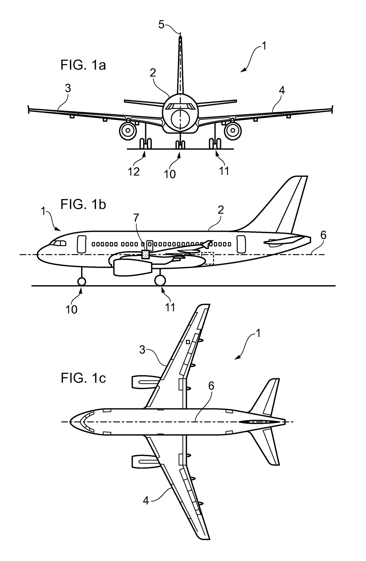
[0031]FIGS. 1a-c show an aircraft 1 having an airframe comprising a fuselage 2 with wings 3, 4 extending outwardly from the fuselage. The airframe has a plane of symmetry 5 containing a longitudinal axis 6 (also known as a roll axis). The aircraft 1 has a centre of gravity 7.

[0032]The aircraft has landing gear which supports the aircraft when it is on the ground and controls the movement of the aircraft during ground manoeuvres such as landing, taxiing and take off. The landing gear comprises a nose landing gear (NLG) assembly 10 forward of the centre of gravity 7, and a pair of port and starboard main landing gear (MLG) assemblies 11, 12 aft of the centre of gravity 7 and arranged either side of the plane of symmetry 5. In other embodiments, the aircraft may comprise further MLG assemblies, typically arranged in pairs and located either side of the plane of symmetry 5. The landing gear is usually retracted when the aircraft 1 is in flight, and extended before landing.

[0033]The NLG...


PUM


Abstract

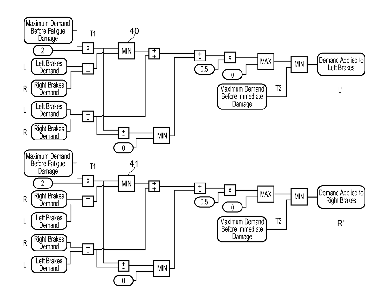
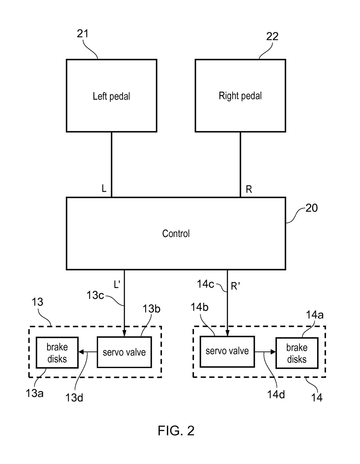
A method of braking left and right landing gear wheels on respective left and right sides of an aircraft. A desired left braking parameter (L) is received for the left wheel and a desired right braking parameter (R) is received for the right wheel. The left wheel is braked with a reduced left braking parameter (L′) which is less than the desired left braking parameter (L), and the right wheel is braked with a reduced right braking parameter (R′) which is less than the desired right braking parameter (R). A difference between the braking parameters is maintained so that L′−R′=L−R.

Description

RELATED APPLICATIONS[0001]The present application claims priority from Great Britain Application Number 1412769.0, filed Jul. 18, 2014, the disclosure of which is hereby incorporated by reference herein in its entirety.FIELD OF THE INVENTION[0002]The present invention relates to a method and associated control system for braking left and right landing gear wheels.BACKGROUND OF THE INVENTION[0003]A typical aircraft has landing gear comprising a plurality of wheeled landing gear assemblies which support the aircraft when it is on the ground. The landing gear assemblies are used to control the movement of the aircraft during ground manoeuvres such as landing, taxiing and take off. A typical large jet-powered aircraft includes a steerable nose landing gear (NLG) assembly located towards the front of the fuselage and a plurality of main landing gear (MLG) assemblies located rearwards of the NLG assembly and distributed laterally about the aircraft's plane of symmetry. The MLG assemblies ...

Claims


Application Information

Patent Timeline
Patent Type & Authority Patents(United States)
IPC IPC(8): B64C25/48B60T8/24B60T8/17B60T8/00B60T8/32
CPCB64C25/48B60T8/00B60T8/246B60T8/1703B60T8/325B64C13/00B60T8/32
Inventor HOWELL, GEORGEBEN, LIVIERROMANA, LOUIS-EMMANUEL
Owner AIRBUS OPERATIONS LTD
Learn More