Thermionic valve tester

a technology of thermionic valve and tester, which is applied in the direction of electrical testing, measurement devices, instruments, etc., can solve the problems of power valve failure, degradation or damage of thermionic valves that may not always be audible, and do not provide for thermionic valve testing, etc., to achieve simple and easy use, and easily be used globally

Active Publication Date: 2017-11-07
ORANGE MUSIC ELECTRONIC COMPANY +1
View PDF10 Cites 0 Cited by
  • Summary
  • Abstract
  • Description
  • Claims
  • Application Information

AI Technical Summary

Benefits of technology

[0014]In a preferred embodiment the first voltage regulator is a switched voltage regulator including a transistor and the controller is adapted to control the pulse width of the transistor so as to alter the voltage supplied by the first voltage regulator to at least one of the valve electrode terminals. Furthermore, the first voltage regulator may be adapted to supply a pulsed HT voltage to a valve anode terminal and the controller may be adapted to monitor current flow in the thermionic valve in response to the pulsed HT voltage, the current flow being representative of thermionic emission of the valve cathode. This enables power to be supplied to the valve electrodes efficiently and in a highly controllably manner and without the disadvantages common to linear regulators of poor efficiency, size and weight so that the valve tester may be easily portable.
[0015]Preferably the second voltage regulator has a switchable connection with a valve heater terminal in the valve socket, the second switched voltage regulator having a transistor and the controller is adapted to control the pulse width of the transistor and to monitor current flow from the second voltage regulator to the valve heater terminal and wherein the controller is further adapted to shut down current supply from the second switched voltage regulator to the valve heater terminal when a high current flow to the valve heater terminal, representative of a short circuit in the valve heater, is detected by the controller. This enables power to be supplied to the valve heater efficiently and in a highly controllably manner and without the disadvantages common to linear regulators of poor efficiency, size and weight.
[0016]In a particularly preferred embodiment the controller further includes a timer and the controller is adapted to delay shutting down current supply to the valve heater terminal for a predetermined time period after high current flow representative of a short circuit is detected. In this way, high inrush currents when a heater is first started can be accommodated by the valve tester so as to avoid false positive test results of a short circuit in the heater.
[0019]The controller is ideally in the form of a processor adapted to perform programmed instructions stored in a program memory. The various valve tests may therefore be stored as one or more algorithms optimized for individual valve types and to minimize power consumption.
[0028]Thus a method and apparatus for testing thermionic valves is provided which is simple and easy to use and enables people other than qualified specialists and audio technicians to regularly monitor valve performance. The valve tester avoids the use of bulky mains transformers and so is a small, portable or handheld unit requiring only a low voltage power supply, as described above. The valve tester can, therefore, easily be used globally as low voltage power supply leads generally have a universal voltage input. Also, where a battery pack is used to power the valve tester, it could be used in conditions where no mains power supply is available, such as at an outdoor concert venue.

Problems solved by technology

However, the method and apparatus described in this document do not provide for testing of the thermionic valve and only provide for adjusting the bias signal to the valve's control grid in order to maintain optimal performance.
There are significant risks associated with a power valve failing during use, for example on stage at a concert, and degradation of or damage to thermionic valves may not always be audibly apparent when a valve is in use in an amplifier.
However the testing of thermionic valves for degradation and damage tends to be limited to qualified specialists and audio technicians.

Method used


Image

  • Thermionic valve tester
  • Thermionic valve tester
  • Thermionic valve tester

Examples


Embodiment Construction

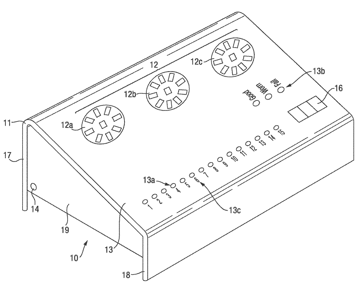
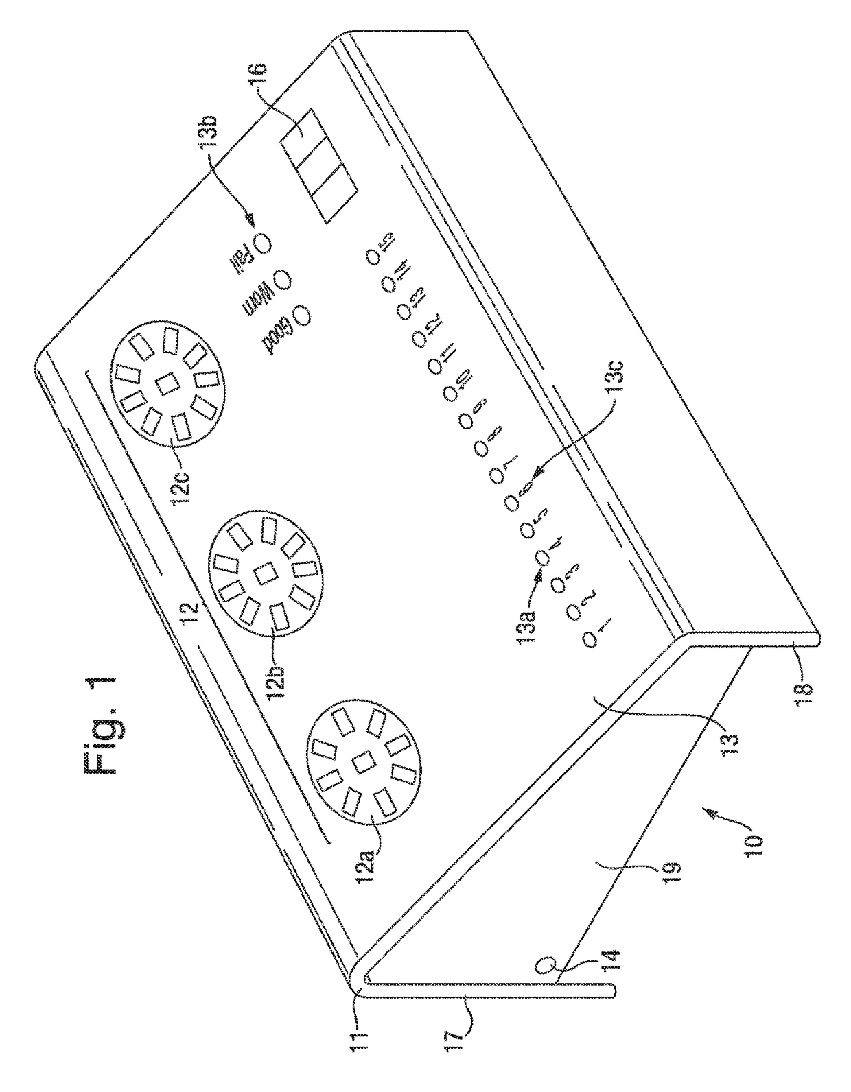
[0034]A device 10 for testing thermionic valves is shown in FIG. 1. The testing device 10 includes a casing 11 which is preferably formed of a lightweight material such as, but not limited to aluminium and a plurality of valve sockets 12 (three are shown in FIG. 1) each of which is adapted to receive and has terminals for connection with the electrode pins of a thermionic valve. Each of the valve sockets 12 has a different arrangement of pin holes to accommodate different types of thermionic valves. For example the first socket 12a is an 8 pin socket and is adapted to connect with power valves, whereas the second socket 12b is a 9 pin socket and is adapted to connect with medium power EL84 valves and the third socket 12c is a 9 pin socket but is adapted for connection with pre-amp valves. In this way the three valve sockets illustrated in FIG. 1 are capable of connecting with a large percentage of the thermionic valves currently used in music amplification equipment. Also, socket ad...


PUM


Abstract

The thermionic valve tester (10) has a casing (11) and three valve sockets (12) each of which is adapted to receive and has terminals for connection with the electrode pins of different types of thermionic valves. The thermionic valve tester (10) also has a display (13) comprising a series of LED lights, three user operated buttons (16), and a single power supply socket or terminal (14) which supplies power to all components of the valve tester and which is adapted for connection to a low voltage DC power supply lead. Internally, the thermionic valve tester (10) has a plurality of voltage regulators each with a switchable connection to at least one valve electrode terminal of the valve sockets (12) and a memory in which is stored the tests and the performance criteria for different types of thermionic valves. A controller controls connection of the voltage regulators with the terminals of the valve sockets (12) and the voltages applied to the terminals and also monitors current flow in the thermionic valve during testing. The thermionic valve tester is a small, portable unit which is simple and easy to use and enables people, other than qualified specialists and audio technicians, to regularly monitor valve performance.

Description

CROSS-REFERENCE TO RELATED APPLICATIONS[0001]This application is a National Stage of International Application No. PCT / IGB2013 / 050716, filed Mar. 19, 2013; which claimed priority to GB 1204876.5, filed on Mar. 20, 2012 and GB 1301193.7, filed on Jan. 23, 2013, the disclosures of which are each incorporated herein by reference.[0002]The present invention relates to apparatus for testing thermionic valves. Particularly, but not exclusively, the present invention relates to apparatus for testing thermionic valves used in audio amplification systems including analogue amplification of musical instruments such as, but not limited to, electric guitars including base guitars.FIELD OF THE INVENTION[0003]Despite advances in solid state technology for the amplification of audio signals, specialist markets continue to exist for the deployment of thermionic devices, in which amplification is achieved by controlling the flow of electrons in an evacuated valve. Power valves are optimized to produ...

Claims


Application Information

Patent Timeline
Patent Type & Authority Patents(United States)
IPC IPC(8): G01R31/25G01R19/00
CPCG01R19/0092G01R31/25G01R31/2825
Inventor COOPER, CLIFFFALLON, ANDREWARROWSMITH, COLIN
Owner ORANGE MUSIC ELECTRONIC COMPANY
Why Eureka
Try Eureka