
Thermionic Valve Tester

a technology of thermionic valve and tester, which is applied in the direction of electrical testing, measurement devices, instruments, etc., can solve the problems of power valve failure, degradation or damage of thermionic valves that may not always be audible, and do not provide for thermionic valve testing, etc., to achieve simple and easy use, and easily be used globally

Active Publication Date: 2015-02-12
ORANGE MUSIC ELECTRONIC COMPANY +1
View PDF4 Cites 2 Cited by
  • Summary
  • Abstract
  • Description
  • Claims
  • Application Information

AI Technical Summary

Benefits of technology

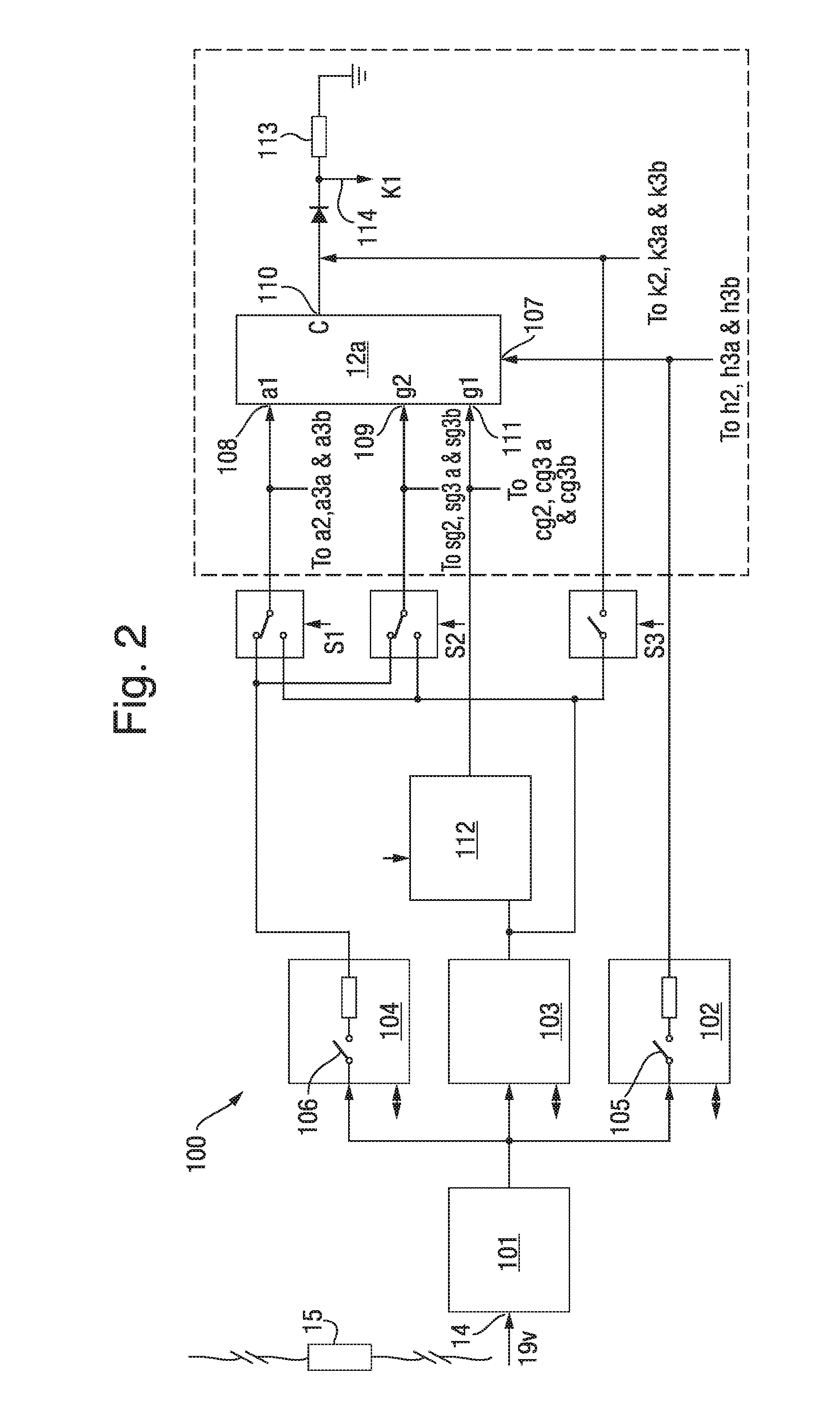
The patent text describes a method and apparatus for testing thermionic valves using a small and portable unit. The valve tester includes a controller that regulates voltage supplied to the valve by using a switched voltage regulator with a transistor. The controller also monitors current flow in the valve to assess its performance. The second voltage regulator has a switchable connection with a valve heater terminal and is controlled by the controller to regulate voltage and monitor current flow. This allows for efficient and controllable power supply to the valve without the use of bulky mains transformers. Additionally, the controller can delay shutting down the current supply to the valve heater terminal to accommodate high inrush currents when the heater is first started. Overall, the valve tester is easy to use and can be used in various environments without requiring a mains power supply.

Problems solved by technology

However, the method and apparatus described in this document do not provide for testing of the thermionic valve and only provide for adjusting the bias signal to the valve's control grid in order to maintain optimal performance.
There are significant risks associated with a power valve failing during use, for example on stage at a concert, and degradation of or damage to thermionic valves may not always be audibly apparent when a valve is in use in an amplifier.
However the testing of thermionic valves for degradation and damage tends to be limited to qualified specialists and audio technicians.

Method used


Image

  • Thermionic Valve Tester
  • Thermionic Valve Tester
  • Thermionic Valve Tester

Examples


Embodiment Construction

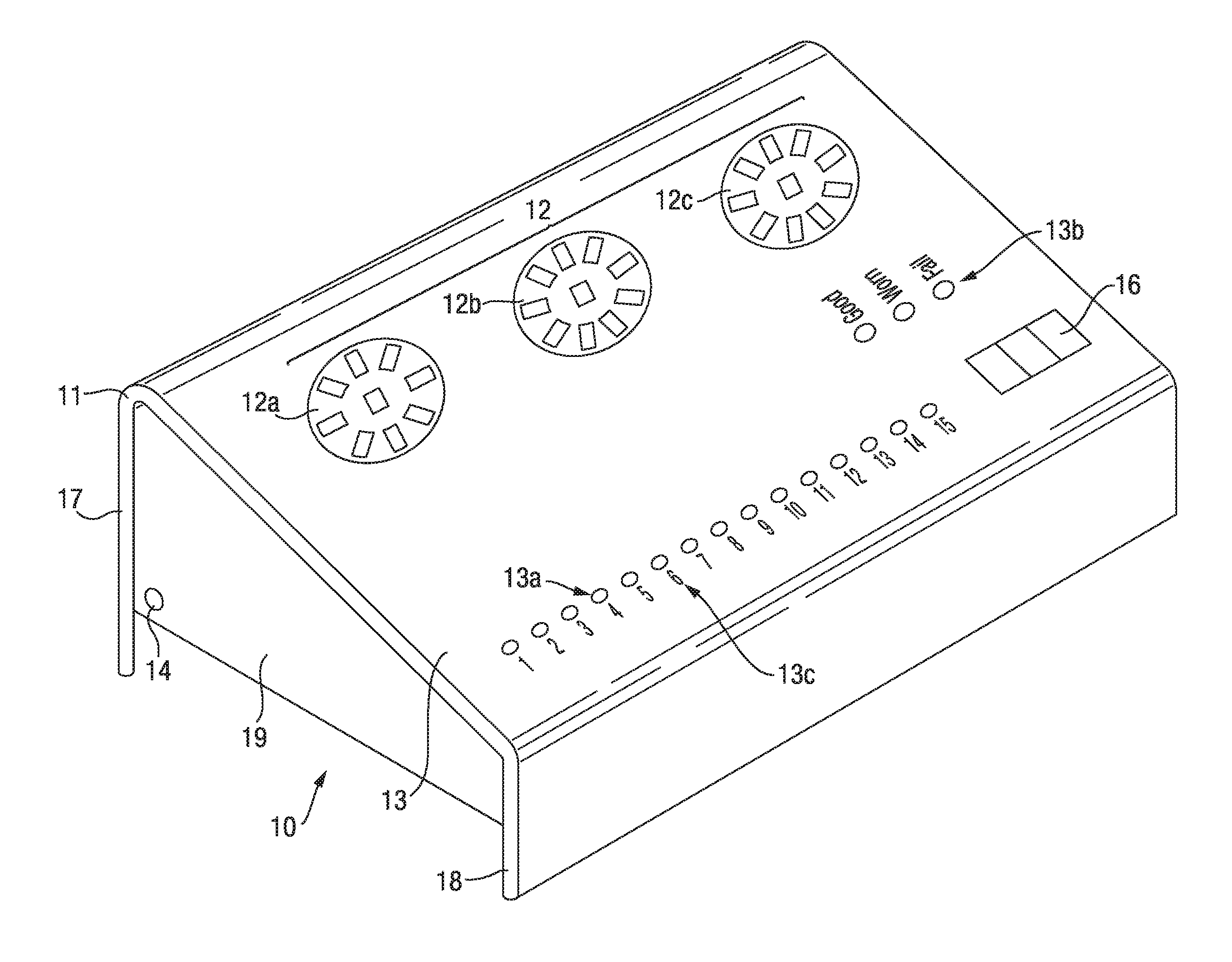
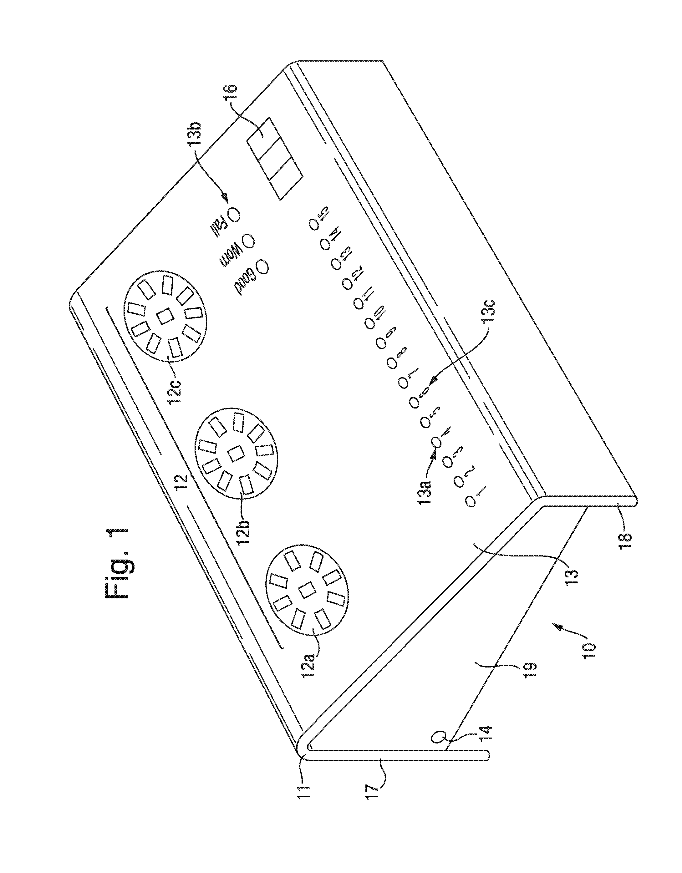
[0033]A device 10 for testing thermionic valves is shown in FIG. 1. The testing device 10 includes a casing 11 which is preferably formed of a lightweight material such as, but not limited to aluminium and a plurality of valve sockets 12 (three are shown in FIG. 1) each of which is adapted to receive and has terminals for connection with the electrode pins of a thermionic valve. Each of the valve sockets 12 has a different arrangement of pin holes to accommodate different types of thermionic valves. For example the first socket 12a is an 8 pin socket and is adapted to connect with power valves, whereas the second socket 12b is a 9 pin socket and is adapted to connect with medium power EL84 valves and the third socket 12c is a 9 pin socket but is adapted for connection with pre-amp valves. In this way the three valve sockets illustrated in FIG. 1 are capable of connecting with a large percentage of the thermionic valves currently used in music amplification equipment. Also, socket ad...


PUM


Abstract

The thermionic valve tester (10) has a casing (11) and three valve sockets (12) each of which is adapted to receive and has terminals for connection with the electrode pins of different types of thermionic valves. The thermionic valve tester (10) also has a display (13) comprising a series of LED lights, three user operated buttons (16), and a single power supply socket or terminal (14) which supplies power to all components of the valve tester and which is adapted for connection to a low voltage DC power supply lead. Internally, the thermionic valve tester (10) has a plurality of voltage regulators each with a switchable connection to at least one valve electrode terminal of the valve sockets (12) and a memory in which is stored the tests and the performance criteria for different types of thermionic valves. A controller controls connection of the voltage regulators with the terminals of the valve sockets (12) and the voltages applied to the terminals and also monitors current flow in the thermionic valve during testing. The thermionic valve tester is a small, portable unit which is simple and easy to use and enables people, other than qualified specialists and audio technicians, to regularly monitor valve performance.

Description

[0001]The present invention relates to apparatus for testing thermionic valves. Particularly, but not exclusively, the present invention relates to apparatus for testing thermionic valves used in audio amplification systems including analogue amplification of musical instruments such as, but not limited to, electric guitars including base guitars.FIELD OF THE INVENTION[0002]Despite advances in solid state technology for the amplification of audio signals, specialist markets continue to exist for the deployment of thermionic devices, in which amplification is achieved by controlling the flow of electrons in an evacuated valve. Power valves are optimized to produce large current swings at the anode for relatively small control grid signals and it is this large output current that is used to drive a loudspeaker via a matching transformer. Such thermionic devices are usually referred to as valves or tubes and will be referred to herein as thermionic valves. To obtain optimum performance...

Claims


Application Information

Patent Timeline
IPC IPC(8): G01R31/25G01R19/00
CPCG01R19/0092G01R31/25G01R31/2825
Inventor COOPER, CLIFFFALLON, ANDREWARROWSMITH, COLIN
Owner ORANGE MUSIC ELECTRONIC COMPANY
Learn More