
Method for determining the exhaust gas temperature of an internal combustion engine

a technology of internal combustion engine and exhaust gas temperature, which is applied in the direction of heat measurement, electric control, instruments, etc., can solve the problems of significant delay of exhaust gas temperature sensor and unsatisfactory high tolerance, and achieve the effect of minimizing tolerance and high dynamic manner

Inactive Publication Date: 2011-09-13
ROBERT BOSCH GMBH
View PDF12 Cites 1 Cited by
  • Summary
  • Abstract
  • Description
  • Claims
  • Application Information

AI Technical Summary

Benefits of technology

The present invention provides an improved method and device for determining the exhaust gas temperature of an internal combustion engine in a highly dynamic manner while minimizing tolerances. The method involves measuring the lambda value of the exhaust gas and calculating the calculated exhaust gas temperature as a function of the measured lambda value and the air mass. The function is then adapted based on multiple comparisons with measured exhaust gas temperatures at different operating points of the internal combustion engine. The invention also takes into account additional parameters such as the rotational speed of the internal combustion engine and the temperature of the internal combustion engine. The invention provides a more accurate and reliable method for determining the exhaust gas temperature of an internal combustion engine.

Problems solved by technology

The disadvantage of the aforementioned method is that the exhaust gas temperature sensor has a significant delay, and therefore reliable protection of the turbocharger through these means may be ensured only to a limited extent.
However, the disadvantage is that the exhaust gas temperature is only imprecisely ascertainable from the lambda value, since this temperature is also dependent on other influencing factors, so that the temperature estimate using the lambda value has a tolerance of approximately + / −50 K. Such a high tolerance is unsatisfactory.

Method used


Image

  • Method for determining the exhaust gas temperature of an internal combustion engine
  • Method for determining the exhaust gas temperature of an internal combustion engine
  • Method for determining the exhaust gas temperature of an internal combustion engine

Examples


Embodiment Construction

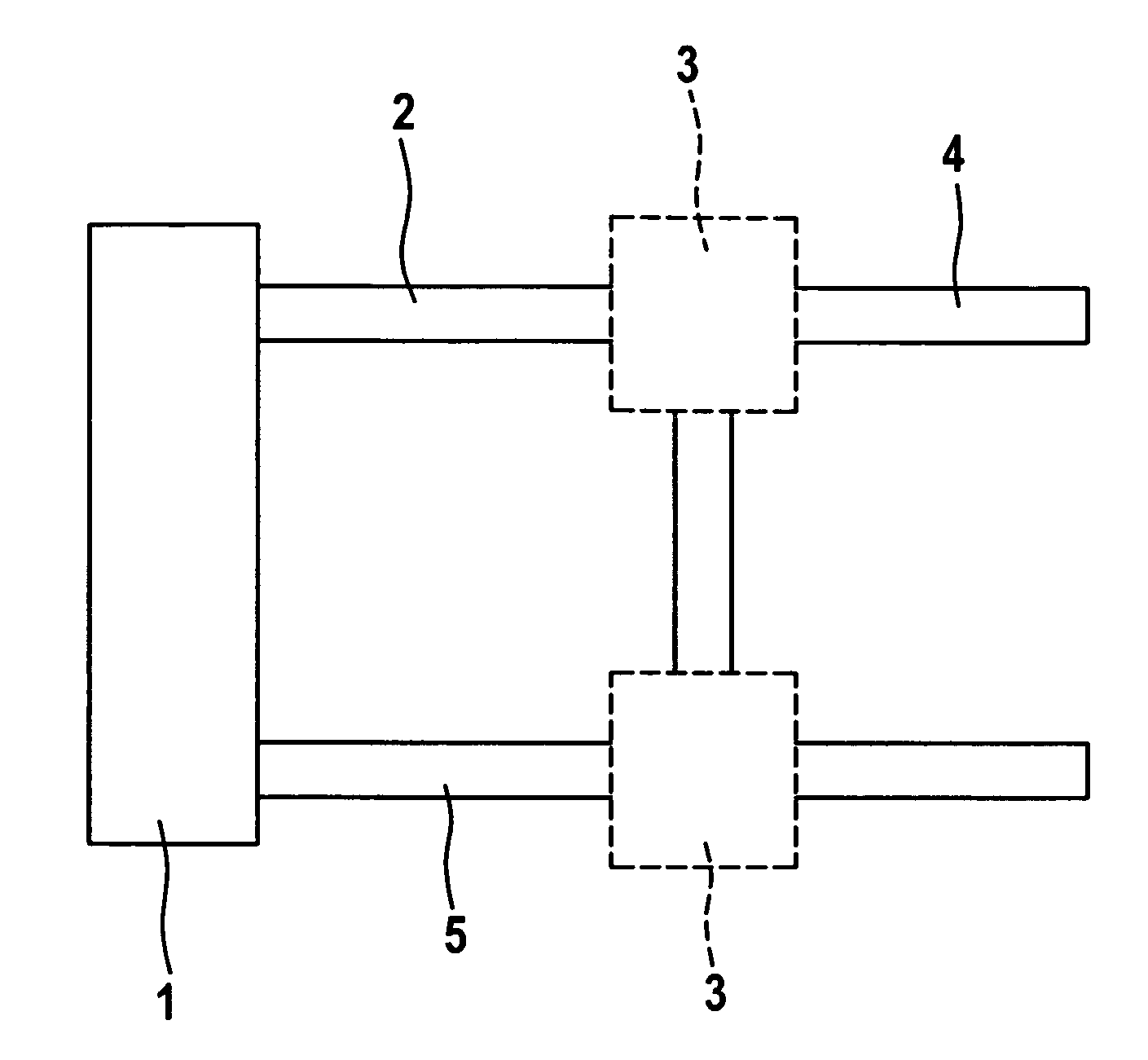
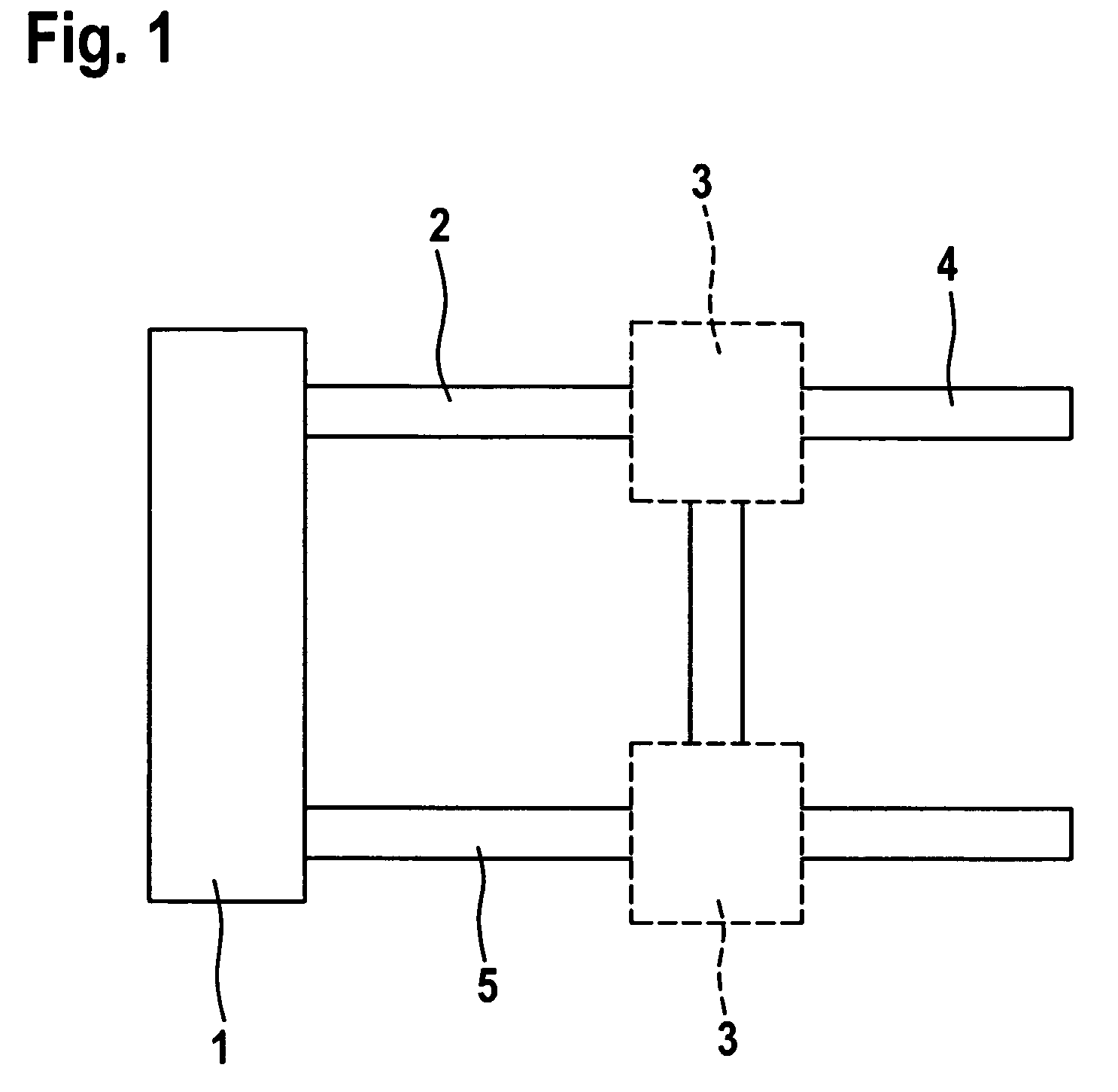
FIG. 1 shows a section of an internal combustion engine including a turbocharger, a combustion chamber 1, an exhaust gas tract 2, a turbocharger 3 and a lambda measuring point 4 being shown. An intake tract 5 is also shown, which supplies air compressed by turbocharger 3 to combustion chamber 1. Exhaust gas tract 2 is connected downstream from combustion chamber 1 and receives the exhaust gas from combustion chamber 1 and passes it on to turbocharger 3. There, the exhaust gas drives a turbine of turbocharger 3. The exhaust gas subsequently reaches lambda measuring point 4, where lambda value λ of the exhaust gas is measured.

A measured exhaust gas temperature T3_test is measured in the exhaust gas tract by an exhaust gas temperature sensor, which is not illustrated. The lambda sensor at lambda measuring point 4 is also not illustrated in detail. However, these sensors are generally known to those skilled in the art. The method according to the present invention is used to prevent ove...


PUM

PropertyMeasurementUnit
temperatureaaaaaaaaaa
exhaust gas temperatureaaaaaaaaaa
rotational speedaaaaaaaaaa

Abstract

A method for determining an exhaust gas temperature of an internal combustion engine, which is performed by measuring a lambda value of the exhaust gas of the internal combustion engine and calculating a calculated exhaust gas temperature as a function of the measured lambda value, and comparing the calculated exhaust gas temperature with a measured exhaust gas temperature and adapting a function used for the calculation as a function of the comparison.

Description

RELATED APPLICATION INFORMATIONThe present application claims priority to and the benefit of German patent application no. 102007042227.1, which was filed in Germany on Sep. 5, 2007, the disclosure of which is incorporated herein by reference.FIELD OF THE INVENTIONThe present invention relates to a method for determining an exhaust gas temperature of an internal combustion engine and to a device for carrying out a method of this type, and also to a computer program.BACKGROUND INFORMATIONTo achieve maximum output in internal combustion engines, turbochargers of the internal combustion engines are operated very close to their thermal limit. To monitor the exhaust temperature (hereinafter also referred to as T3), an exhaust gas temperature sensor may be used to vary combustion parameters of the internal combustion engine if the turbocharger is at risk of overheating.The disadvantage of the aforementioned method is that the exhaust gas temperature sensor has a significant delay, and the...

Claims


Application Information

Patent Timeline
Patent Type & Authority Patents(United States)
IPC IPC(8): G01K15/00G01D18/00
CPCF02D41/1446F02D41/1447F02D41/1454G01K7/42G01K13/02F02D41/2451F02D2200/0608G01K2205/04
Inventor MOSER, EDUARDDENCKER, FLORIAN
Owner ROBERT BOSCH GMBH
Learn More