Permanent magnet laminated motor with axial spacer ring vents

a laminated motor and permanent magnet technology, applied in the direction of magnetic circuit rotating parts, dynamo-electric machines, magnetic circuit shapes/forms/construction, etc., can solve the problems of large amount of materials and low utilization rate of silicon steel sheets, and achieve the effect of reducing the consumption of structure materials, reducing the utilization rate of silicon steel sheets, and increasing specific power

Active Publication Date: 2017-11-07
SHANGHAI ZHENGQIAN TECH CO LTD
View PDF11 Cites 2 Cited by
  • Summary
  • Abstract
  • Description
  • Claims
  • Application Information

AI Technical Summary

Benefits of technology

[0006]To solve the problems of the existing technology, the present invention aims to provide a permanent magnet laminated motor to reduce the weight and the volume of the motor, thus improve the specific power.
[0035]By adopting the foregoing technical solutions, the motor of the present invention has far greater specific power than the common cartridge-type motor and disc motor, it also leads to motor weight loss and volume reduction which improve the utilization rate of silicon steel sheet and effectively minimize the consumption of structure materials. In addition, the self-cooling effect of this motor is better; especially making more sense by saving materials and reducing weight for large motor (especially for large wind power generator). Motor of the present invention is particularly suitable for transportations.

Problems solved by technology

However, in general the volume of current existing motor is very huge, which results in consuming large amounts of materials during the production, and the low utilization rate of silicon steel sheet makes it uneconomic.

Method used


Image

  • Permanent magnet laminated motor with axial spacer ring vents
  • Permanent magnet laminated motor with axial spacer ring vents
  • Permanent magnet laminated motor with axial spacer ring vents

Examples


Embodiment Construction

[0058]Embodiments of the invention will be described in detailed with reference to accompanying drawings.

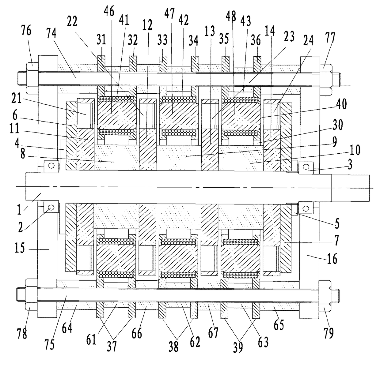
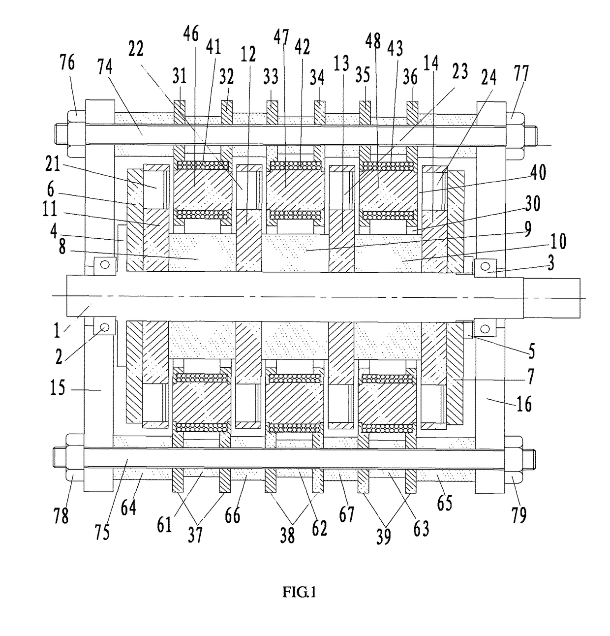
[0059]As FIG. 1-FIG. 10 shows, the invention, a permanent magnet laminated motor, comprising: two end plates 15,16 arranged in parallel; a rotating shaft 1 rotatably arranged between the two end plates 15,16 by two bearings 2,3; n+1 rotor units and n spacer rings alternately fixedly sleeved orderly on the outer rim of the rotating shaft 1; two magnetic conductive rings 6,7 tightly sleeved on the outer rim of the rotating shaft 1 and tightly attached to the outer side of the outermost two of the rotor units respectively; and n stator units respectively sleeved on the outer rims of the spacer rings correspondingly, wherein the same axial air gaps 40 is provided between each stator unit and the adjacent rotor unit, and the edges of stator units are axially fixedly connected to the two end plates 15,16 by several installation screws, n for natural number.

[0060]In this embodiment, tak...


PUM


Abstract

A permanent magnet laminated motor includes two end plates (15,16) arranged in parallel; a rotating shaft (1) rotatably arranged between the two end plates (15,16); n+1 rotor units (11, 12, 13, 14) and n spacer rings (8, 9, 10) alternately fixedly sleeved on outer rims of the rotating shaft (1) and axially compacted; two magnetic conductive rings (6, 7) tightly sleeved at the outer rim of the rotating shaft (1) and tightly attached to the outer side of the outermost two rotor units (11, 14); and n stator units (37, 38, 39) respectively sleeved at the outer rims of the spacer rings (8, 9, 10). An axial air gap (40) is provided between each stator unit (37, 38, 39) and the adjacent rotor unit (11, 12, 13, 14), and the n stator units (37, 38, 39) are axially fixedly connected to the two end plates (15, 16) by installation screw rods (74, 75).

Description

CROSS REFERENCE TO RELATED APPLICATION[0001]This U.S. National Stage Patent Application claims the benefit of International Application Serial No. PCT / CN2013 / 081635 filed on Aug. 16, 2013 and CN Patent Application No. CN 201210324131.6 filed on Sep. 4, 2012, the entire disclosures of which are incorporated herein by reference.BACKGROUND OF THE INVENTION1. Field of the Invention[0002]The present invention relates to a permanent magnet motor, particularly to a permanent magnet laminated motor with axial magnetic circuits.2. Description of Related Art[0003]Generally a generator is cartridge-shaped with its cylindrical rotor and cartridge-shaped stator being coaxial. For the convenience of output, the armature is always located outside as a stator. The specific power (power generated by unit weight of a motor) of this kind of generator is about 0.2 kw / kg, the specific power of the aviation generator could be up to 0.5 kw / kg.[0004]However, in general the volume of current existing motor ...

Claims


Application Information

Patent Timeline
Patent Type & Authority Patents(United States)
IPC IPC(8): H02K16/00H02K21/24H02K1/27
CPCH02K16/00H02K21/24H02K1/2793H02K1/2796
Inventor CHEN, MOQUANZHANG, BINGYIWEI, LEHAN
Owner SHANGHAI ZHENGQIAN TECH CO LTD
Why Eureka
Try Eureka