Thrust vector control

a technology of thrust vector and control, applied in the direction of influencers using magnus effect, propulsive elements, applications, etc., can solve the problems of not insubstantial loss of thrust power, relatively small clearance, and only effective use of thrust vector control, so as to improve controllability and reduce the effect of thrust power loss

Active Publication Date: 2017-11-14
AIRBUS DEFENCE & SPACE
View PDF5 Cites 5 Cited by
  • Summary
  • Abstract
  • Description
  • Claims
  • Application Information

AI Technical Summary

Benefits of technology

[0006]Embodiments of the present invention provide a thrust vector control which provides an improved controllability with the least possible loss of thrust power and simultaneously also provides controllability at low engine thrust.
[0015]Due to the provision of a driven rotational body, e.g., a quickly rotating cylinder, a Magnus effect can be generated which laterally deflects the flow field, i.e., the thrust current. In other words, the Magnus effect, which arises due to the rotating cylinder, induces a control of the direction vector of the thrust current, i.e. a thrust vector control.
[0025]With regard to the guide plates, these are for example the previously used adjustment elements, which provide, as a supplement to the Magnus effect caused by the rotational body, an additional deflection, i.e., a further improved thrust vector control.
[0029]The provision of a distance between one or more guide plates and one or more rotational bodies can guarantee that the thrust current is deflected over as much of the total cross-sectional area as possible corresponding to the desired control.
[0031]As a further example, a configuration is provided in which the thrust vector control has guide plates next to the rotational body or bodies: If these, i.e. the guide plates are set in the neutral position, i.e., in the direction of the thrust current of the propulsion stream without deflection, the rotating cylinders have little to no effect, i.e., there is little to no deflection. At a certain deflection of the guide plates, e.g. already at a small deviation from the neutral position, the effectiveness of the guide plates is proportionally increased by the Magnus effect up to the position in which the guide plates are almost in contact with the lateral surface.
[0049]According to a further aspect of the invention, a rotating rotational body is introduced at a thrust current in order to achieve a deflection of the airflow or the thrust current by the Magnus effect. Due to the Magnus effect, there arise thereby only minimal output losses from the thrust of the thrust current. As the Magnus effect already occurs at low air speeds or fluid velocities, controllability already arises at low thrusts. An increased controllability can be provided at low engine thrust, e.g., during a landing approach or during failure of one or more engines, because a possible deflection is provided which is improved, in comparison to conventional control flaps, i.e., by extending over a greater angular region, by the Magnus effect. The inventive thrust vector control can be provided in different directions by the arrangement of corresponding rotational bodies, such that it is possible to forgo additional lateral flaps or pitch elevators in the case of aircraft and despite this be able to control different flight maneuvers such as the previously mentioned landing approach. The inventive thrust vector control can be used for an aircraft and also for stabilizing the aircraft, such that a conventional tail unit can be completely done away with.

Problems solved by technology

The thrust vector control is, however, only effectively usable if a drive unit provides a corresponding thrust current.
However, it has been shown that thrust nozzles, in particular, for use on aircraft, have only a relatively small clearance for movement, and thus provide a possible deflection of the thrust current in only a small angular segment.
In addition, a deflection of the thrust current caused for example by control flaps generally results in a not insubstantial loss of thrust power due to the aerodynamic, or with regard to jet drives, hydrodynamic turbulences arising therefrom.

Method used


Image

  • Thrust vector control
  • Thrust vector control
  • Thrust vector control

Examples


Embodiment Construction

[0006]Embodiments of the present invention provide a thrust vector control which provides an improved controllability with the least possible loss of thrust power and simultaneously also provides controllability at low engine thrust.

[0007]Accordingly, embodiments are directed to a thrust vector control for a vehicle having a fluid drive, a vehicle having a fluid drive, and a method for controlling a fluid-driven vehicle.

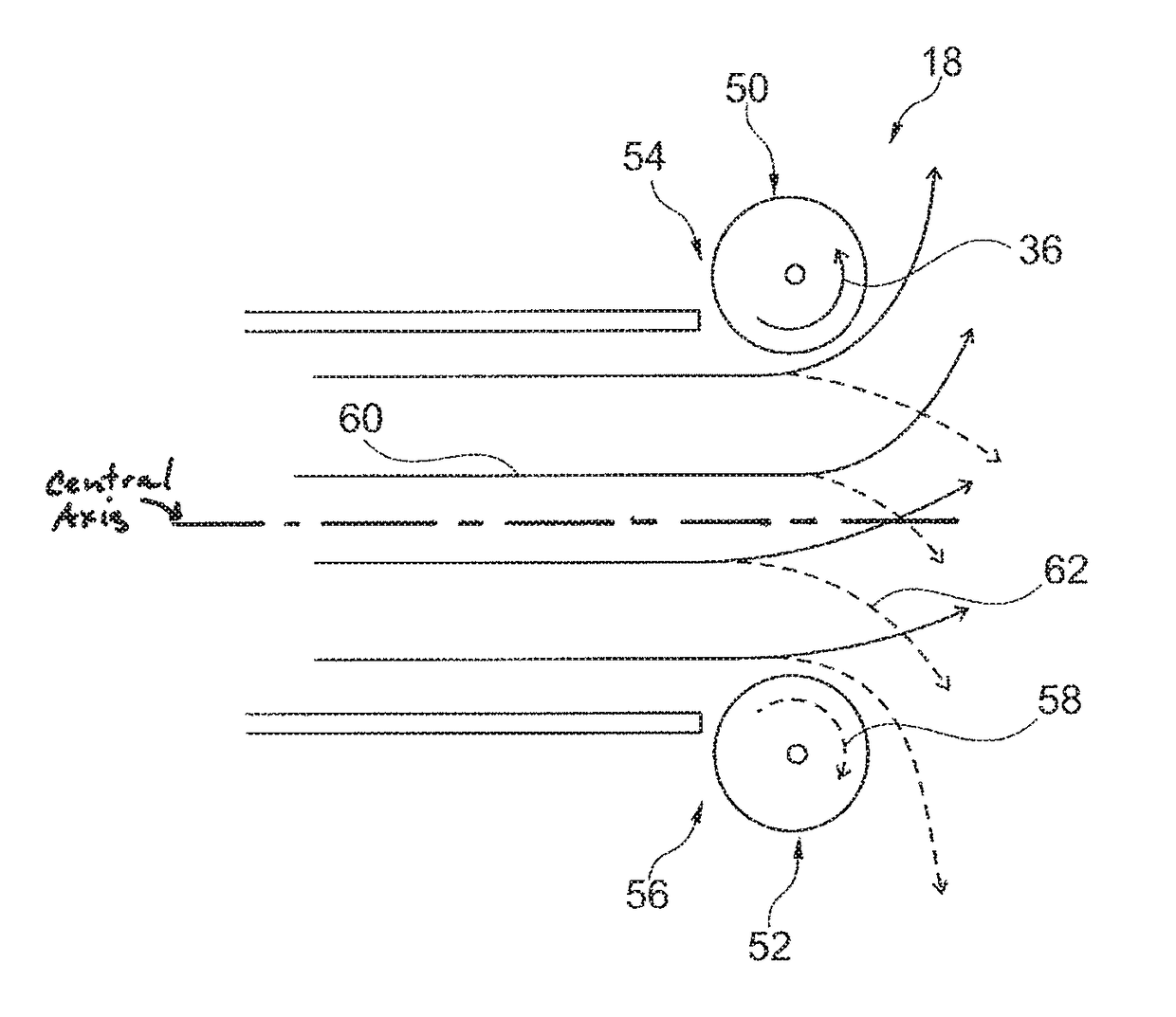
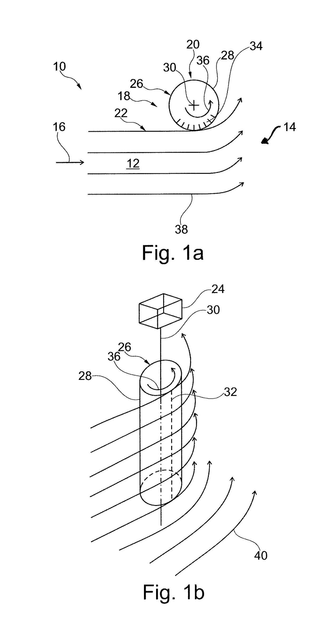
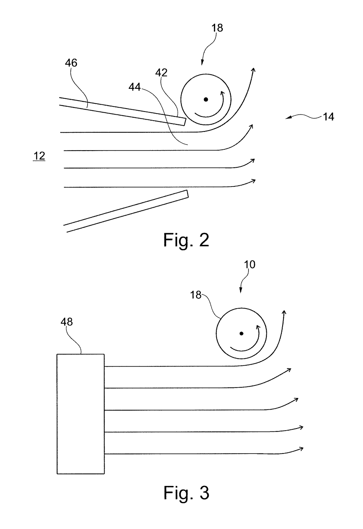
[0008]According to a first aspect of the invention, a thrust vector control is provided for a vehicle having a fluid drive. The thrust vector control has a thrust current region for a thrust current of a propulsion stream which has a flow direction. In addition, the thrust vector control has a steering mechanism for the thrust current. The steering mechanism has at least one steering device, which is arranged at least in a peripheral region of the thrust current region. The at least one steering device has a rotational body driven by a drive, said body having a later...


PUM


Abstract

Thrust vector control for a vehicle having a fluid drive, vehicle having thrust vector control and method of controlling thrust vector. Thrust vector control includes a thrust current region for a thrust current of a propulsion stream having a flow direction; a steering mechanism for the thrust current including at least one steering device arranged at least in a peripheral region of the thrust current region, and the at least one steering device includes a rotational body with a lateral surface and a rotational axis arranged transverse to the flow direction, and the rotational body being rotatable so that a first part of the lateral surface exposed to the thrust current rotates in a first rotational direction, whereby a Magnus effect is produced to deflect the thrust current. The first rotational direction is in a direction of the thrust current.

Description

CROSS-REFERENCE TO RELATED APPLICATIONS[0001]The present application claims priority under 35 U.S.C. §119(a) of German Patent Application No. 10 2011 120 855.4 filed Dec. 13, 2011, the disclosure of which is expressly incorporated by reference herein in its entirety.BACKGROUND OF THE INVENTION[0002]1. Field of the Invention[0003]The present invention relates to a thrust vector control for a vehicle having a fluid drive, a vehicle having a fluid drive, and a method for controlling a fluid-driven vehicle.[0004]2. Discussion of Background Information[0005]A thrust vector control is used, e.g., to control vehicles into a specific direction. For example, thrust vector controls are used for aircraft and also rockets. In addition, thrust vector controls are also used for watercraft and land vehicles, e.g., for jet-driven boats or also for so-called airboats, on which a propeller device generates a rearward airflow that can directed laterally by vertical flaps in order to control the airboa...

Claims


Application Information

Patent Timeline
Patent Type & Authority Patents(United States)
IPC IPC(8): F02K9/80B64C23/08F02K1/00
CPCF02K9/80F02K1/008B64C23/08
Inventor SEIFERT, JOST
Owner AIRBUS DEFENCE & SPACE
Why Eureka
Try Eureka