Fall away arrow rest system

a technology of falling away arrows and rests, which is applied in the field of falling away arrow rest systems, can solve the problems of reducing accuracy, prone to failure, and complex and intricate construction of fall away arrow rests, so as to facilitate the use of the arrow rest, slow down the bow string, and reduce the effect of angular momentum

Active Publication Date: 2017-11-14
BLACK GOLD ARCHERY LLC
View PDF27 Cites 13 Cited by
  • Summary
  • Abstract
  • Description
  • Claims
  • Application Information

AI Technical Summary

Benefits of technology

[0008]The torsional biasing element, ball detent and the wall obstruction can all be configured to operate the arrow rest. When the launcher is in its lowered position (and the activator component is in the first position), the launcher can be rotated upward toward the upright arrow support position. Upon reaching this position, the activator component is in the second position and can be configured to remain in the second position due to the wall obstruction preventing the ball detent from passing underneath. However, when the launcher is rotated further back into the drawn position, the activator component can also rotate further back into the third position. When the activator component is released from the third position, the torsional biasing element urges the activator component forward back toward the second position. Due to the rotational momentum of the activator upon reaching the second position, the ball detent depressed upon contact with the wall obstruction and the activator component is free to travel from the second position to the first position. During this rotation, the launcher can rotate from the drawn upright position to the upright arrow support position to the lowered position.
[0009]The foregoing sequence of positions can correspond to the firing of an arrow by a user of the bow. In order to facilitate the use of the arrow rest with the bow, the arrow rest can include a cord mount having a cord connected to the bow string of the bow. Thus, when the bow string is drawn and pulled back, the cord mount causes the shaft of the arrow rest to rotate, thereby causing rotation of the launcher and the activator component. When the user fully draws back the bow string, the launcher is in the drawn position and the activator component is in the third position. If the user decides to fire the arrow by releasing the string, the activator component rotates toward the second position where ball detent depresses underneath the wall obstruction allowing the activator component to continue rotation to the first position. During this time, the launcher rotates to its lowered position allowing the arrow to pass by the launcher without being obstructed. If however, the user decides not to fire the drawn arrow, the user can slowly let back the bow string. During this movement, the activator component rotates back toward the second position. However, the reduced angular momentum of the activator component prevents the ball detent from depressing and the wall obstruction prevents the activator component from rotating beyond the second position. Thus, the launcher remains in the upright arrow support position so that the arrow rest can continue supporting the unfired arrow.

Problems solved by technology

A common problem with traditional arrow rests is that the fletching of the arrow would contact the arrow rest as the arrow passed through the rest upon firing of the bow.
This would result in a change of trajectory and flight path of the arrow, thereby reducing accuracy.
However, the designs for fall away arrow rests that are currently used in art contain inherent limitations.
One common problem is that fall away arrow rests contain a complex and intricate construction of parts that can easily malfunction and are prone to failure, especially in rugged environments commonly encountered by bow hunters.
Another common problem with currently used fall away arrow rests art is that they do not remain in an upright position when the string of a drawn bow is let down after the user decides not to fire.
As a result, the arrow does not remain steadied such that the user may quickly redraw the bow and fire the arrow.

Method used


Image

  • Fall away arrow rest system
  • Fall away arrow rest system
  • Fall away arrow rest system

Examples


Embodiment Construction

[0027]The invention will now be described with reference to the drawing figures, in which like reference numerals refer to like parts throughout. For purposes of clarity in illustrating the characteristics of the present invention, proportional relationships of the elements have not necessarily been maintained in the drawing figures.

[0028]The following detailed description of the invention references specific embodiments in which the invention can be practiced. The embodiments are intended to describe aspects of the invention in sufficient detail to enable those skilled in the art to practice the invention. Other embodiments can be utilized and changes can be made without departing from the scope of the present invention. The present invention is defined by the appended claims and the description is, therefore, not to be taken in a limiting sense and shall not limit the scope of equivalents to which such claims are entitled.

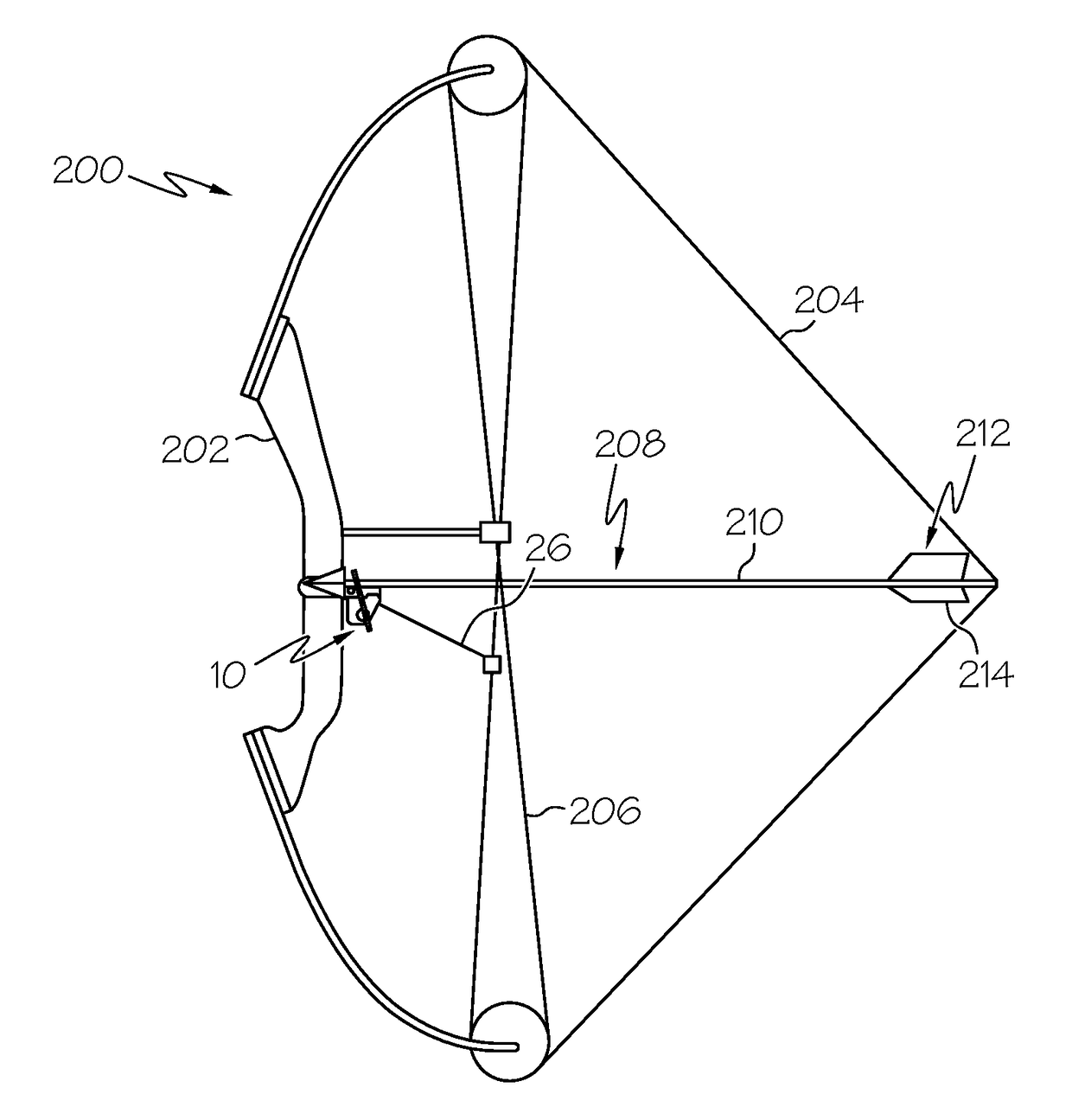
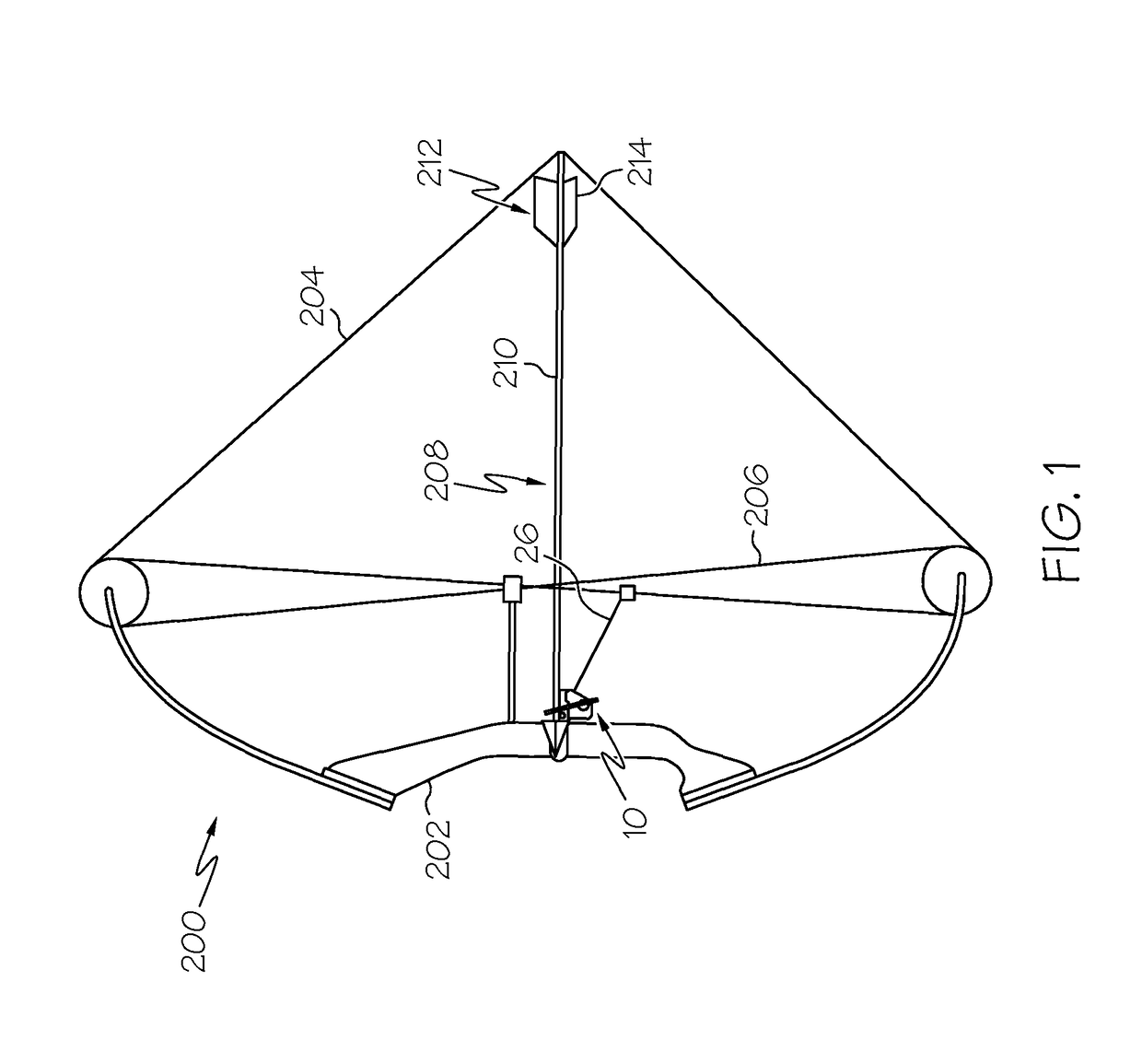
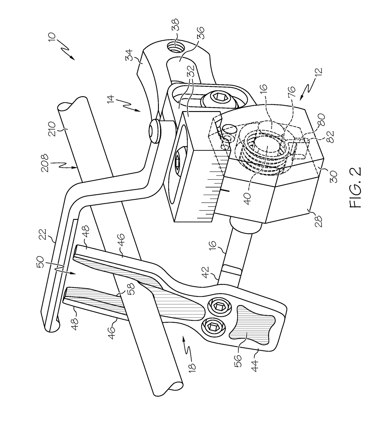
[0029]The present invention is directed generally to an imp...


PUM


Abstract

An arrow rest device for bows and similar equipment is provided. The arrow rest can include a y-shaped launcher, a shaft and a housing with an activator. The launcher and the activator can be fixedly connected to the shaft and rotate therewith. Within the housing can be a wall with an obstruction that can be shaped and designed to interact with a ball detent or similar component located on the end of the activator. The activator can be configured to rotate inside the housing wall and can be coupled to the housing with a biasing element that urges rotation of the activator and shaft in one direction. The activator can rotate in the housing between three positions, each corresponding to an orientation of the launcher. In one position, the activator is maintained by the wall so as to allow the launcher to have an upright orientation for supporting an arrow.

Description

CROSS-REFERENCE TO RELATED APPLICATIONS[0001]This Application claims priority to U.S. Provisional Patent Application Ser. No. 62 / 188,241, filed on Jul. 2, 2015, to Michael J. Ellig, entitled “Fall Away Arrow Rest System,” the entire disclosure of which is incorporated herein by reference.BACKGROUND OF THE INVENTION[0002]Arrow rests for compound bows enable a user to more easily and more accurately draw, aim, and fire an arrow at a directed target. The rest provides the user with a steady surface on which the user can place the shaft of the arrow while preparing to fire the bow so that the user need not be concerned about dropping the arrow. In addition, arrow rests enable the user to make aiming adjustments based on the surrounding environmental conditions (e.g., wind speed and direction) while reducing the tendency of dropping the arrow.[0003]A common problem with traditional arrow rests is that the fletching of the arrow would contact the arrow rest as the arrow passed through the...

Claims


Application Information

Patent Timeline
Patent Type & Authority Patents(United States)
IPC IPC(8): F41B5/22F41B5/14
CPCF41B5/143
Inventor ELLIG, MICHAEL J.LARSON, PHILLIP
Owner BLACK GOLD ARCHERY LLC
Why Eureka
Try Eureka