Gun/rifle sight for tracking a moving object

a technology for moving objects and rifle sights, which is applied in the direction of sighting devices, weapons, weapon components, etc., can solve the problems of failing to describe a gun/rifle sight and a prior patent that does not provide a gun/rifle sight, so as to achieve the effect of quick change, easy determination of lead time, and quick alteration of lead time for aiming

Inactive Publication Date: 2017-11-14
SHAMROCK INT FASTENER LLC
View PDF8 Cites 1 Cited by
  • Summary
  • Abstract
  • Description
  • Claims
  • Application Information

AI Technical Summary

Benefits of technology

[0004]Further, U.S. Pat. No. 6,321,479 to Sheehan discloses a sighting device having an aperture with a series of visual reference points framing the aperture that are used in concert with a vertical front sight to quickly acquire and precisely aim a firearm at a target. The visual reference points framing the aperture are readily discernable to a shooter, even though the reference points and the aperture may be visually out of focus as the shooter concentrates on the target. The visual reference points framing the aperture are in the form of edges, angles, and vertices that take advantage of the human eye's natural acuity for angular geometric shapes as the shooter visually coordinates the position of the present invention with the vertical front sight and a target. The unobstructed field of view provided by the aperture portion of the present invention combined with readily discernable geometrically shaped visual reference points framing the aperture assist the shooter in precisely aiming a firearm, or other projectile propulsion device, at a target. In addition, rapid and accurate adjustments, or refinements, in the shooter's aim at a target are readily effected with the present invention.
[0014]In yet another advantage of the present gun sight for tracking a moving object is that the present gun sight for tracking a moving object may have a first and second spring clip which allows the gun sight to easily and quickly be secured to the barrel of a gun.

Problems solved by technology

However, the prior patents fail to describe a gun / rifle sight for tracking moving objects which is easy to use and efficient as is described in the present application.
Further, these patents fail to provide a gun / rifle sight for tracking moving objects by easily selecting a preset lead time by altering the position of a sight.

Method used


Image

  • Gun/rifle sight for tracking a moving object
  • Gun/rifle sight for tracking a moving object
  • Gun/rifle sight for tracking a moving object

Examples


Embodiment Construction

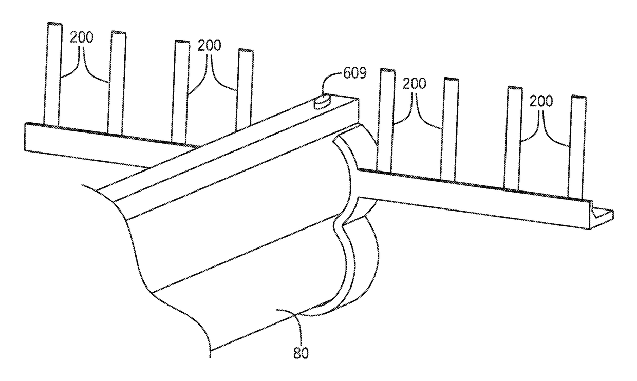
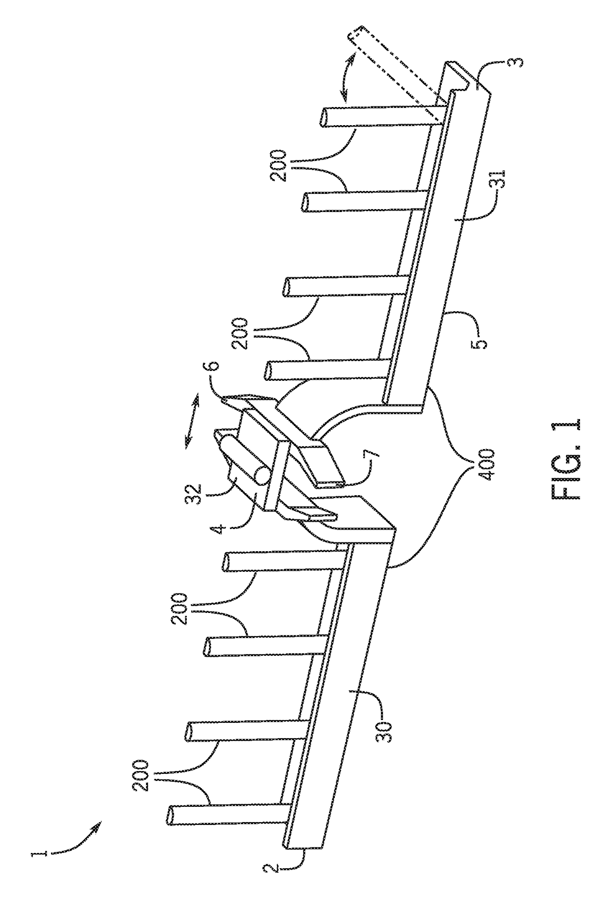
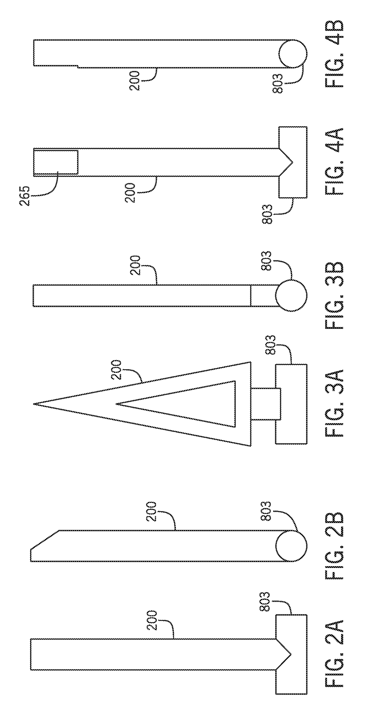
[0036]A gun / rifle sight for tracking a moving object is provided. The gun sight may have a generally elongated frame secured at a distal end of a barrel of a gun in a perpendicular manner with respect to the barrel. In a first embodiment, the gun sight has plurality of pegs which independently and selectively move from a downward orientation to an upward orientation so as to allow a user to gauge the lead time for firing the gun at the moving object. In a second embodiment, a plurality of stationary pegs is secured in a staggered manner around a rotating cylindrical cover. When the cylindrical cover is rotated around the elongated stationary frame, only a single stationary peg may be moved to an upward orientation at a given time therein allowing the user to select the lead time for firing the gun at the moving object.

[0037]Referring first to FIG. 1, in a first embodiment a gun / rifle sight 1 for tracking a moving object 100 (FIG. 13) is provided. The gun sight 1 may be generally mad...


PUM


Abstract

A gun / rifle sight for tracking a moving object is provided. The gun sight may have a generally elongated frame secured at a distal end of a barrel of a gun in a perpendicular manner with respect to the barrel. In a first embodiment, the gun sight has plurality of pegs which independently and selectively move from a downward orientation to an upward orientation so as to allow a user to gauge the lead time for firing the gun at the moving object. In a second embodiment, a plurality of stationary pegs is secured in a staggered manner around a rotating cylindrical cover. When the cylindrical cover is rotated around the elongated stationary frame, only a single stationary peg may be moved to an upward orientation at a given time.

Description

[0001]A gun / rifle sight for tracking a moving object is provided. The gun sight may have a generally elongated frame secured at a distal end of a barrel of a gun in a perpendicular manner with respect to the barrel. In a first embodiment, the gun sight has plurality of pegs which independently and selectively move from a downward orientation to an upward orientation so as to allow a user to gauge the lead time for firing the gun at the moving object. In a second embodiment, a plurality of stationary pegs is secured in a staggered manner around a rotating cylindrical cover. When the cylindrical cover is rotated around the elongated stationary frame, only a single stationary peg may be moved to an upward orientation at a given time therein allowing the user to select the lead time for firing the gun at the moving object.[0002]Providing sights for gun for tracking moving targets is known in the prior art. For example, U.S. Pat. No. 8,978,287 to Riley discloses a shotgun sight for mount...

Claims


Application Information

Patent Timeline
Patent Type & Authority Patents(United States)
IPC IPC(8): F41G1/00F41G11/00F41G1/033F41G1/473
CPCF41G1/473F41G11/004F41G1/033
Inventor WAICHULIS, ROBERT
Owner SHAMROCK INT FASTENER LLC
Why Eureka
Try Eureka