Work vehicle with enhanced implement position control and bi-directional self-leveling functionality

a technology of position control and implement, which is applied in the direction of mechanical machines/dredgers, soil shifting machines/dredgers, constructions, etc., can solve the problems of previously disclosed automatic control systems, material being inadvertently dumped from implements, and tasks that are often quite challenging for operators

Active Publication Date: 2017-11-21
BLUE LEAF I P INC
View PDF42 Cites 21 Cited by
  • Summary
  • Abstract
  • Description
  • Claims
  • Application Information

AI Technical Summary

Problems solved by technology

Unfortunately, this task is often quite challenging for the operator and can lead to materials being inadvertently dumped from the implement.
However, such previously disclosed automatic control systems still suffer from many drawbacks, including poor system responsiveness and imprecise implement position control.
In particular, previously disclosed control systems have been unable to properly accommodate the non-linearity of the operational dynamics of the lift assembly as the loader arms are being moved, thereby providing less than desirable results.

Method used


Image

  • Work vehicle with enhanced implement position control and bi-directional self-leveling functionality
  • Work vehicle with enhanced implement position control and bi-directional self-leveling functionality
  • Work vehicle with enhanced implement position control and bi-directional self-leveling functionality

Examples


Embodiment Construction

[0015]Reference now will be made in detail to embodiments of the invention, one or more examples of which are illustrated in the drawings. Each example is provided by way of explanation of the invention, not limitation of the invention. In fact, it will be apparent to those skilled in the art that various modifications and variations can be made in the present invention without departing from the scope or spirit of the invention. For instance, features illustrated or described as part of one embodiment can be used with another embodiment to yield a still further embodiment. Thus, it is intended that the present invention covers such modifications and variations as come within the scope of the appended claims and their equivalents.

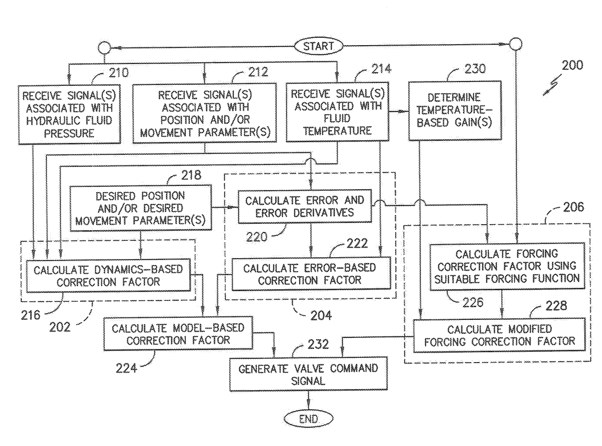
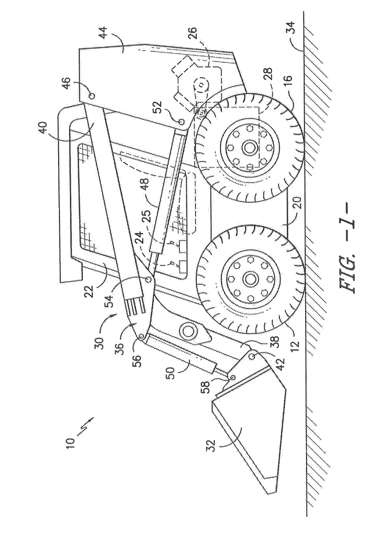
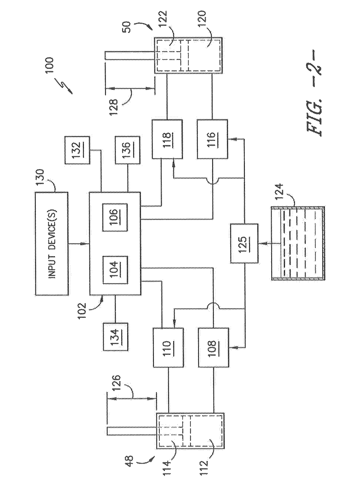
[0016]In general, the present subject matter is directed to systems and methods for automatically adjusting the position of an implement of a work vehicle in order to maintain the implement at a fixed or constant angular orientation relative to a given refe...


PUM


Abstract

A method for automatically adjusting the position of an implement of a lift assembly may generally include receiving a signal indicative of a position and / or a movement parameter of loader arms of the lift assembly and receiving a signal indicative of a pressure of a hydraulic fluid supplied within the lift assembly. The method may also include calculating a first correction signal associated with adjusting the position of the implement, wherein the correction signal is calculated by inputting the position and / or the movement parameter and the fluid pressure into a control equation based on a model of the operational dynamics of the lift assembly. In addition, the method may include generating a valve command signal based at least in part on the correction signal and transmitting the valve command signal to a valve for maintaining the implement at a fixed orientation relative as the loader arms are being moved.

Description

FIELD OF THE INVENTION[0001]The present subject matter relates generally to work vehicles and, more particularly, to a system and method for automatically adjusting the orientation or angular position of an implement of a work vehicle using closed-loop control so as to provide bi-directional self-leveling functionality as the vehicle's boom or loader arms are being moved.BACKGROUND OF THE INVENTION[0002]Work vehicles having lift assemblies, such as skid steer loaders, telescopic handlers, wheel loaders, backhoe loaders, forklifts, compact track loaders and the like, are a mainstay of construction work and industry. For example, skid steer loaders typically include a lift assembly having a pair of loader arms pivotally coupled to the vehicle's chassis that can be raised and lowered at the operator's command. In addition, the lift assembly includes an implement attached to the ends of the loader arms, thereby allowing the implement to be moved relative to the ground as the loader arms...

Claims


Application Information

Patent Timeline
Patent Type & Authority Patents(United States)
IPC IPC(8): E02F3/43E02F9/20
CPCE02F9/2029E02F3/433
Inventor SINGH, ADITYAWU, DUQIANGGULATI, NAVNEET
Owner BLUE LEAF I P INC
Why Eureka
Try Eureka