Operating device for motor vehicles

a technology for operating devices and motor vehicles, applied in the direction of electronic switching, pulse technique, construction, etc., can solve the problems of problematic arrangement and positioning of such sensor assemblies on the vehicl

Active Publication Date: 2017-11-28
HUF HULSBECK & FURST GMBH & CO KG
View PDF10 Cites 0 Cited by
  • Summary
  • Abstract
  • Description
  • Claims
  • Application Information

AI Technical Summary

Benefits of technology

[0017]The formation of such an electrically conductive separating device on the exterior surface improves the separate detectability of the individual sensor actuations and the temporal sequence of the proximities. Depending on the type of sensor, the sensitivity of the capacitive sensors, or the magnetic field sensors, is spatially delimited, such that an overlapping of the sensitive region of one sensor on that of an adjacent sensor is reduced. By way of example, sensors spaced at a few centimeters apart can be disposed in a plane, and a plastic chrome plated barrier is disposed between the detection regions. The metal-plated barrier acts as a shield for the electrical field of a capacitive sensor, such that the sensitivity is concentrated on the region above the sensor, thus the region of the plastic cover of the sensor. The barrier also counteracts an overlapping for the sensor regions for static and low-frequency magnetic fields.
[0020]In a preferred design, the plastic cover for the sensors is designed such that it is continuous in the detection plane. The plastic cover thus covers all of the sensor devices. The electrically conductive separating device faces toward the detection, and is attached to this continuous plastic cover, e.g. it is glued thereto, or attached thereto with other attachment means. The electrically conductive detection device thus does not need to separate the plastic covers of the individual sensor devices from one another; it is sufficient when it is placed on the exterior of the plastic cover, and separates the detection regions there.
[0021]In another design of the invention, the plastic covers of the individual sensors are formed separately, and placed between the conductive separating devices. In this manner, it is possible to obtain a flatter structural design of the sensor device.
[0022]In a further development of the invention, a light source, or waveguide coupled to a light source, is disposed beneath the separating device. An illumination of the electrically conductive separating device of this type makes it possible to reliably locate the actuation regions, and detect the separations thereof, even in the dark. By way of example, EP 2067665 discloses a possibility for illuminating such an electrically conductive separating device, wherein the separating device is designed as a manufacturer logo.
[0026]The important thing about the invention is that a technical improvement regarding the separation of the detection regions is obtained, while at the same time, an improved design possibility for the operating device is also made available. Both the plastic cover as well as the electrically conductive separating device may have an aesthetic design, wherein, for example, a vehicle logo or manufacturer logo may be formed by the metallic separating part. In this manner, the operating device can be integrated in the vehicle logo, and the plastic cover region, thus the regions between the metallic separating devices, are the active sensor surfaces. This device then fulfills a design purpose, as well as resulting in an improved and easily locatable operating device for the vehicle user. If such a vehicle logo is then also illuminated according to the invention, then the actuation region can be easily found in any situation. Because the operating device is no longer installed at concealed locations, but instead, can be placed at prominent locations on the vehicle, the operability is improved. Vehicle logos are frequently disposed at precisely those positions at which an actuation would be desirable, but which otherwise prevent the attachment of a sensor device. The integration of the sensor device in the logo itself enables a double functionality, and simplifies the operation thereof.

Problems solved by technology

The arrangement and positioning of such sensor assemblies on a vehicle is problematic because the sensors should be easy to operate and access, without jeopardizing the structural integrity of the vehicle or the aesthetic appearance.

Method used


Image

  • Operating device for motor vehicles
  • Operating device for motor vehicles

Examples


Embodiment Construction

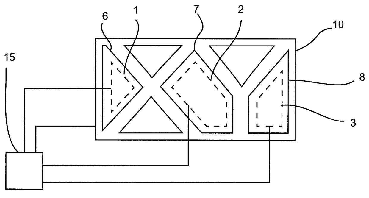
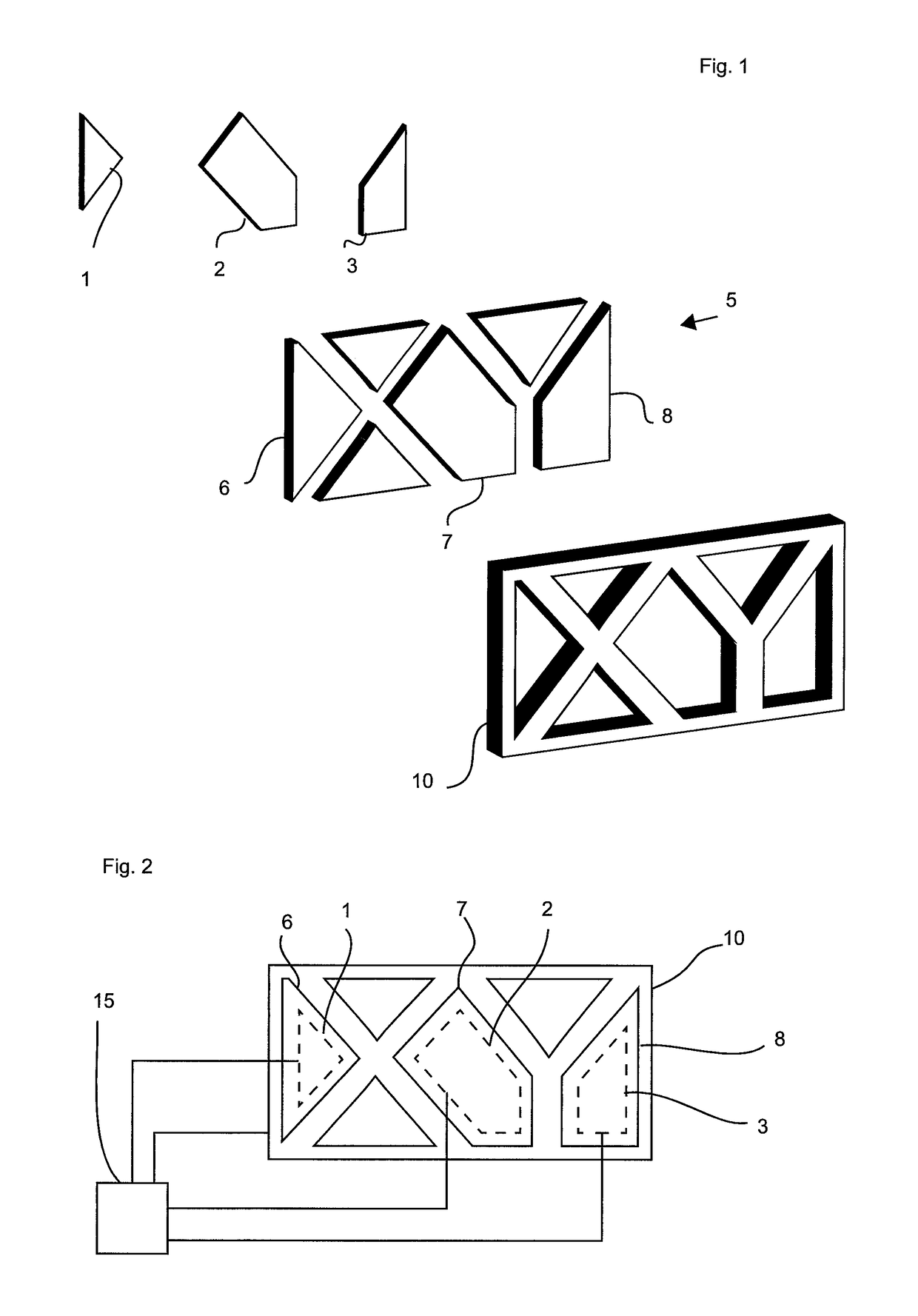
[0030]Three differently shaped sensor electrode sections 1, 2, 3 are depicted in FIG. 1. These sensor electrodes are formed from a metallic plate. Numerous electrically insulating plastic covers 5 are shown. It can be seen that the sensor electrodes 1, 2, 3 are adapted to the shape of the plastic covers 6, 7 and 8, respectively. The sensors electrodes 1, 2, 3 are smaller thereby, such that edge areas remain exposed in each case, when the sensor electrodes are disposed beneath the plastic covers. The plastic covers thus overlap the sensor electrodes at all sides. A metallic separating device 10 is adapted in terms of its shape to the plastic parts 5, such that the plastic parts act as inserts in the empty spaces in the metallic cover 10. When the electrodes 1, 2, 3 are placed behind the respective plastic covers 6, 7 and 8, they are then separated on all sides from the metallic separating device 10. The metallic separating device 10 is designed as an emblem for a vehicle manufacturer...


PUM


Abstract

An operating device for a motor vehicle includes a plurality of proximity sensors for detecting contactless actuation. The operating device extends in a first plane and the sensors are disposed in that plane, separated from one another and oriented with their detection regions in the same spatial direction. A control and evaluation device is coupled to the sensors for detection of signals from each of the sensors. The sensors are covered with at least one electrically insulating plastic cover and, thus, separated from the detection region. At least one electrically conductive separating device is disposed between the sensors and oriented toward the side facing the detection regions, and directly adjacent to the plastic cover.

Description

BACKGROUND[0001]The invention relates to an operating device for motor vehicles. In particular, the invention relates to an operating device for detecting the proximity of users of motor vehicles, wherein the operating device has numerous proximity sensors.[0002]Various detection devices for user access of motor vehicles are known. In particular, optical and capacitive sensor devices are known that detect the proximity of a user or the body part of a user.[0003]By way of example, WO2013 / 117386 describes a device and a detection method having numerous sensor electrodes with which the accessing of a vehicle hatch is detected. The sensor assembly disclosed therein is designed for detecting movement gestures on a motor vehicle, wherein two sensor electrode assemblies are disposed at spatially offset positions on the motor vehicle. The sensor electrodes are designed as elongated electrode assemblies, and a control and evaluation device registers the changes in the capacitance detected by...

Claims


Application Information

Patent Timeline
Patent Type & Authority Patents(United States)
IPC IPC(8): G01D5/24H03K17/96E05F15/76
CPCG01D5/24E05F15/76H03K17/9622H03K2217/960765H03K2217/96079H03K2217/960755E05Y2900/532
Inventor SCHINDLER, MIRKOVAN GASTEL, PETERGERDES, BERND
Owner HUF HULSBECK & FURST GMBH & CO KG
Why Eureka
Try Eureka