Electric machine
a technology of electric machines and electric motors, applied in the field of electric machines, can solve the problems of inability to reduce production costs, inability to improve manufacturing speed, and drawbacks of electric machines, and achieve the effects of reducing cogging torque, simple structure, and reducing magnetic loss
- Summary
- Abstract
- Description
- Claims
- Application Information
AI Technical Summary
Benefits of technology
Problems solved by technology
Method used
Image
Examples
first embodiment
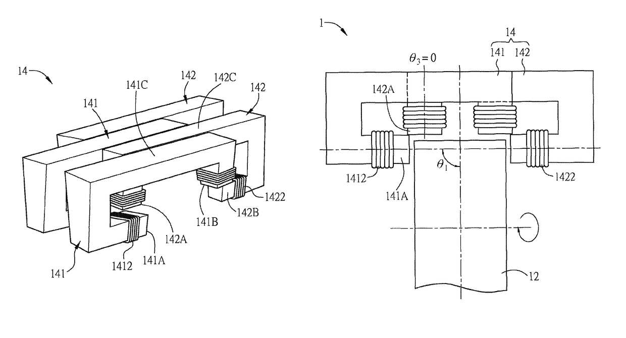
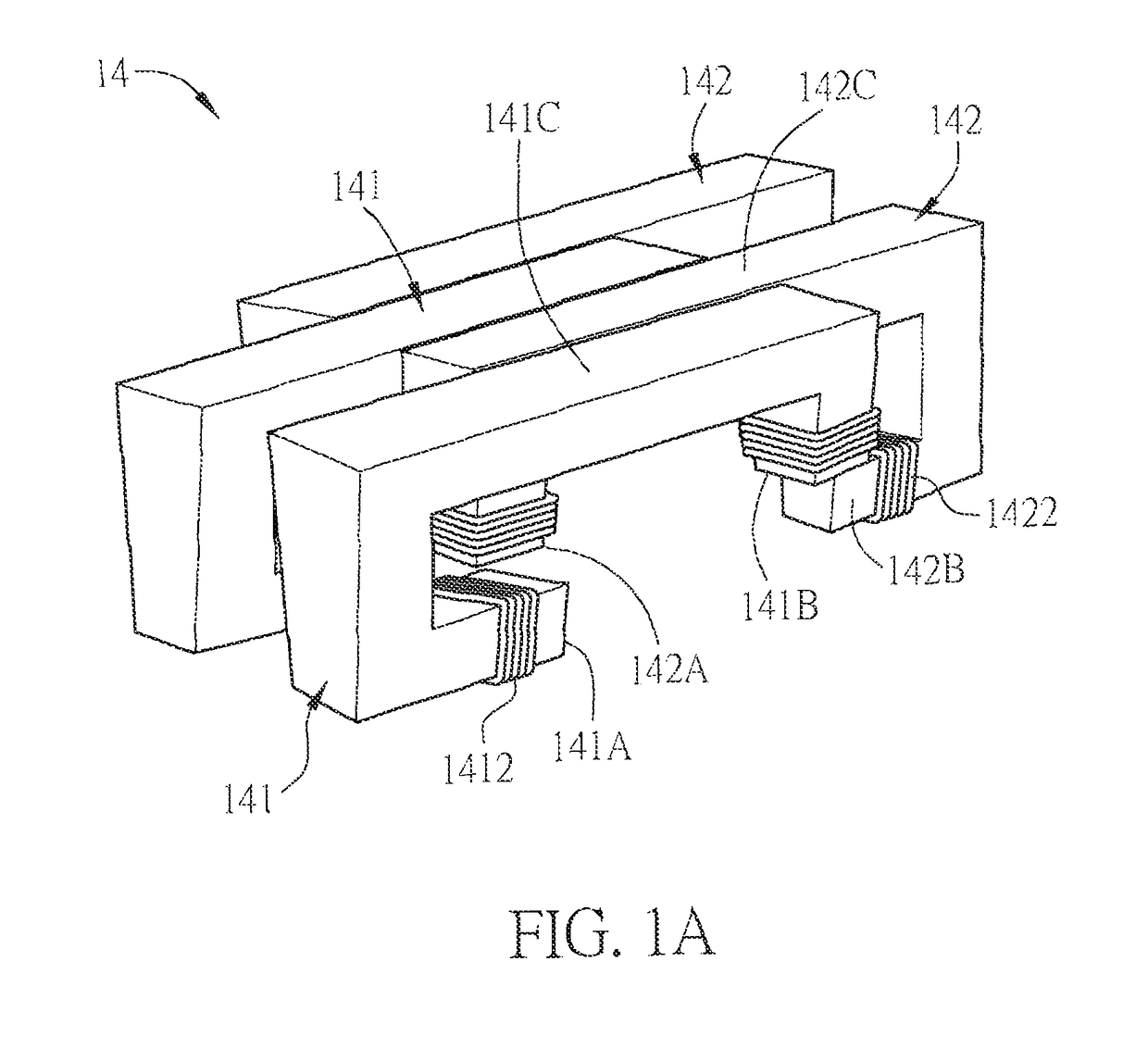
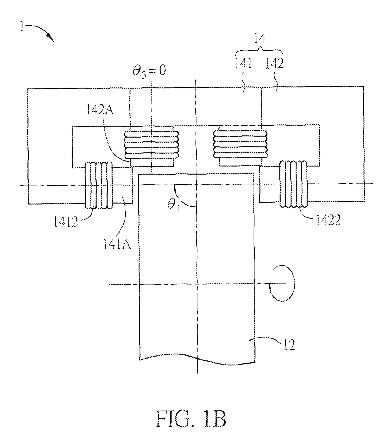
[0045]FIGS. 1A to 1C are schematic diagrams, a front view and a side view of a stator according to the invention.
[0046]Referring to FIGS. 1A to 1C, an electric machine 1 according to a first embodiment of the invention includes a rotor 12 and a stator 14. The stator 14 is disposed near to the rotor 12, and includes at least a first stator unit 141 and at least a second stator unit 142, and the stator units are adjacently disposed or adjacently arranged. For the sake of easy description, the figures only show two first stator units 141 and two second stator units 142, and the magnets inside the rotor 12 are omitted. The first stator unit 141 and the second stator unit 142 are alternately arranged or misaligned. Besides, the first stator unit 141 and the adjacent second stator unit 142 are tightly placed together and substantially have no gap therebetween.
[0047]To be noted, the term “adjacently disposed” or “adjacently arranged” means that the stator units 141 and 142 are disposed alo...
second embodiment
[0060]FIG. 2A is a schematic diagram showing a stator 24 according to the invention, and FIG. 2B is a front view of the stator 24 of FIG. 2A in cooperate with a rotor 22. For the sake of clear illustration, the coils 2412 and 2422 of the first stator unit 241 and the second stator unit 242 are omitted in FIG. 2A, and the winding methods thereof can be referred to FIG. 2B. FIG. 2B also shows a magnet (not labeled) embedded in the rotor 22, so that it will not be detached from the rotor 22 in high-speed rotation and can provide a uniform magnetic force for operation.
[0061]Different from the first embodiment, the front ends of the teeth of the first stator units 241 and the second stator units 242 of the stator 24 have slanted surfaces. In other words, the front ends of the first tooth 241A of the first stator unit 241 and the third tooth 242A of the second stator unit 242, which are adjacently disposed, substantially align to a coplanar surface, thereby forming a substantially continu...
third embodiment
[0064]FIG. 3A is a schematic diagram showing a stator 34 according to the invention, and FIG. 3B is a front view of the stator 34 of FIG. 3A. To be noted, for clearly illustrating the third angle θ3, the second stator unit 342 is shown in the front in FIG. 3B, and the relative position between the first stator unit 341 and the second stator unit 342 is still the same.
[0065]Different from the second embodiment, the protruding directions of the front ends of the first tooth 341A of the first stator unit 341 and the third tooth 342A of the second stator unit 342 are the same. In the third embodiment, a protruding length L1 of the first tooth 341A of the first stator unit 341 is different from the protruding length L2 of the third tooth 342A of the second stator unit 342. In other words, the front ends of the first tooth 341A and the third tooth 342A have the same included angle (90 degrees) with the radial direction of the rotor (not shown), but the protruding lengths of the front edge...
PUM
 Abstract
Description
Claims
Application Information
 - R&D
- Intellectual Property
- Life Sciences
- Materials
- Tech Scout
- Unparalleled Data Quality
- Higher Quality Content
- 60% Fewer Hallucinations
Browse by: Latest US Patents, China's latest patents, Technical Efficacy Thesaurus, Application Domain, Technology Topic, Popular Technical Reports.
© 2025 PatSnap. All rights reserved.Legal|Privacy policy|Modern Slavery Act Transparency Statement|Sitemap|About US| Contact US: help@patsnap.com


