Motor

A technology of salient poles and coils, applied in the direction of electromechanical devices, electrical components, electric components, etc., can solve the problems that the induced voltage waveform affects the controllability, it is impossible to achieve high-speed rotation, increase the eddy current, etc., and reduce the cogging effect Effects of torque, prevention of waveform distortion, and reduction of distortion of induced voltage waveform

Inactive Publication Date: 2010-05-05
PANASONIC CORP
View PDF3 Cites 0 Cited by
  • Summary
  • Abstract
  • Description
  • Claims
  • Application Information

AI Technical Summary

Problems solved by technology

[0005] However, although the concentrated winding motor disclosed in Japanese Patent Laid-Open No. 2000-245085 has the advantage of realizing high torque, it has the problem that the waveform distortion is found in the reverse voltage (reverse voltage). When the waveform skew of the voltage increases, the eddy current will be increased, which will increase the iron loss and reduce the efficiency
In this structure, the circumferential dimension of the front end of the salient pole is smaller than the effective width of the permanent magnet circumferential direction, and since the coils of the stator are wound intensively, there is a problem that skew occurs in the induced voltage waveform, which affects the controllability, and , as the rotation speed increases, the peak value of the skewed waveform becomes larger and rises rapidly. Since the peak voltage exceeds the allowable voltage, it is impossible to achieve high-speed rotation due to the limitation of the voltage.

Method used


Image

  • Motor
  • Motor
  • Motor

Examples


no. 1 Embodiment

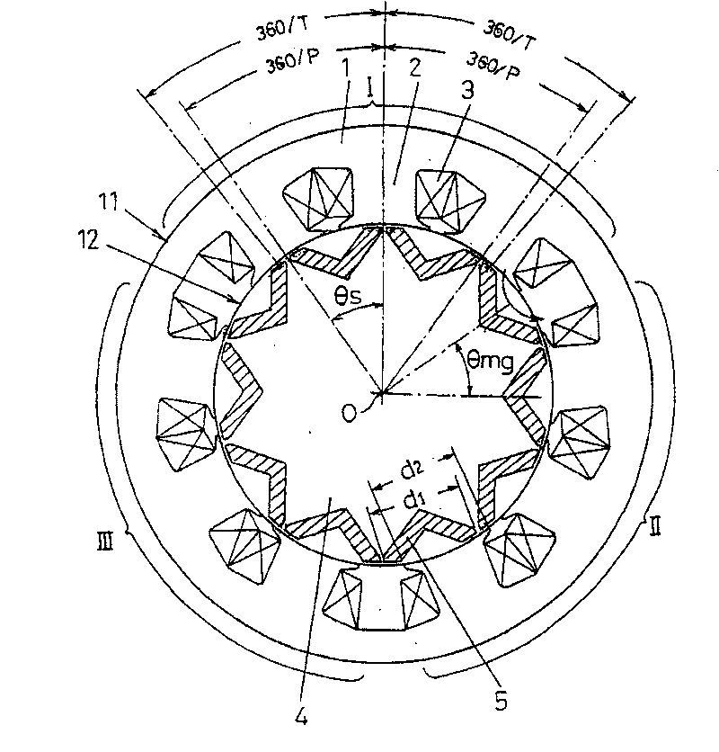
[0029] refer to figure 1 , figure 2 A first embodiment of the motor of the present invention will be described. In order to illustrate the motor structure of this embodiment, figure 1 , figure 2 It is a cross-sectional view of main parts cut along a plane perpendicular to the rotation center axis of the motor. figure 1 , figure 2 Among them, a stator core 1 composed of laminated electromagnetic steel sheets has a plurality of salient poles 2 , and coils 3 are wound around the salient poles 2 . The configuration of the coil 3 is a three-phase coil, and each phase is constituted by three coils 3 in the illustrated example. These three coils 3 of the same phase are arranged at consecutive positions, and the coil 3 in the middle is wound in a reverse winding direction with respect to the coils 3 adjacent to each other. The three coils 3 of this winding method are connected in series or in parallel, and the coil groups of each phase are arranged with a phase difference ...

no. 2 Embodiment

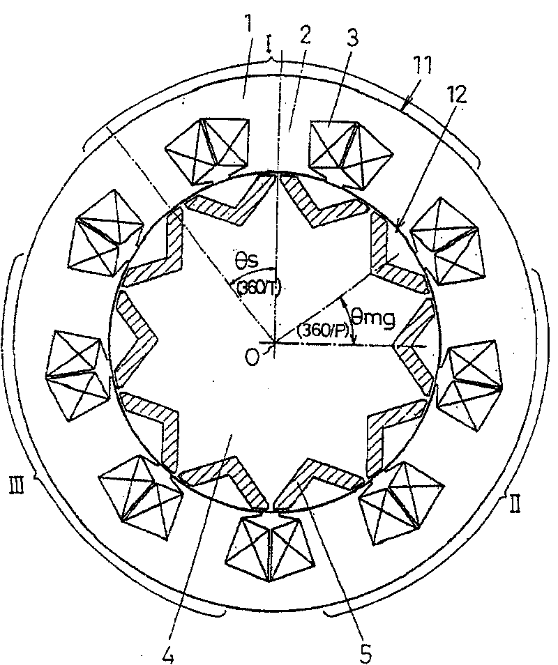
[0050] Refer below image 3 A second embodiment of the motor of the present invention will be described. In the description of the following embodiments, the same reference numerals are assigned to the same components as those of the above-mentioned embodiments, and the description thereof will be omitted, and the differences will be mainly described.

[0051] image 3 In this embodiment, when the arrangement angle of the salient poles 2 in each salient pole group I, II, III is not 360 / T(deg), that is, 360 / P(deg)≤θs(deg)<360 / T( deg), the relationship between the slot angle os1(deg) between the salient poles 2 and 2 in each salient pole group I, II, and III and the arrangement angle θs(deg) of the salient pole 2 is set to satisfy the following formula,

[0052] θs / 5(deg)>os1≥θs / 7(deg)

[0053] By adjusting the legs 6 of the adjacent salient poles 2 and 2 between the salient pole groups I, II and III, the slotting angle os2( deg), set to satisfy the following formula.

[0...

no. 3 Embodiment

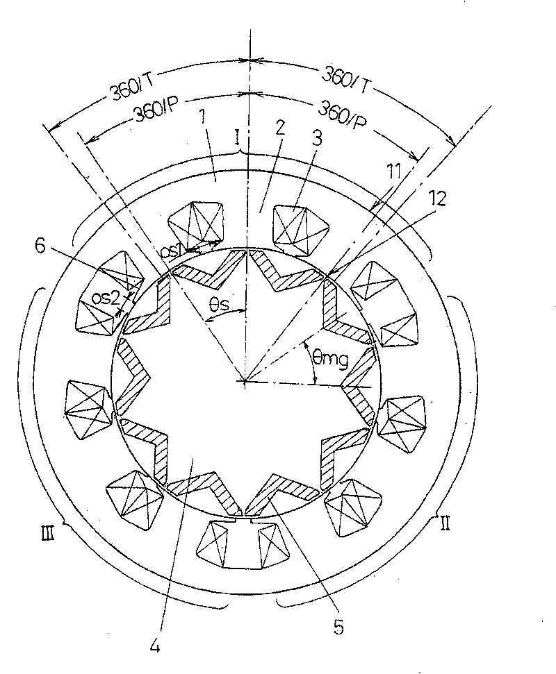
[0058] Refer below Figure 4 A third embodiment of the motor of the present invention will be described.

[0059] Figure 4 In this embodiment, when the disposition angle θs (deg) of the salient poles 2 in each salient pole group I, II, III is inconsistent with the disposition angle (360 / P(deg)) of the permanent magnet 5, that is, 360 / P (deg)<θs(deg)≤360 / T(deg), in order to eliminate the difference in magnetic flux density caused by the phase difference between the salient poles 2 and 2 in each salient pole group I, II, III, each The cross-sectional area of ​​the winding portion of the coil 3 of the salient pole 2 is formed such that the cross-sectional area w2 of the salient pole 2 located on the front side is smaller than the cross-sectional area w1 of the salient pole 1 located on the rear side in the rotation direction of the rotor 12, and the The cross-sectional area w3 of the salient pole 2 positioned further forward is made smaller.

[0060] With this structure, the ...


PUM


Abstract

The motor comprises a stator, in which windings are wound around each of a plurality of stator teeth provided on a stator core, and a rotor, in which a plurality of permanent magnets that exceeds thenumber of stator teeth are disposed at equal intervals around a periphery of a rotor core. In this motor, the stator teeth are arranged into a plurality of stator teeth groups, in which the windings to which the same phase voltage is applied are positioned adjacent to one another, and the windings on adjacent stator teeth in the group are wound in opposite directions. Furthermore, an interpolar angle Theta s(deg) between the stator teeth within each stator teeth group is set to any angle that satisfies the requirement: 360/P(deg)<=Theta s(deg)<=360/T(deg) where T is the total number of statorteeth and P is the total number of permanent magnets. A motor is provided, which produces a high level of torque, displays minimal distortion of the induced voltage waveform, and is capable of being optimized in accordance with the required levels of controllability and cogging torque.

Description

technical field [0001] The present invention relates to a motor, in particular to a motor applicable to battery electric vehicles (PEV), hybrid electric vehicles (HEV), fuel cell vehicles (FCEV) and the like, as well as home appliances and robots. Background technique [0002] Conventionally, as a motor suitable for electric battery vehicles (PEV), hybrid electric vehicles (HEV), fuel cell vehicles (FCEV), etc., a concentrated winding embedded magnet type motor is known (for example, refer to Japanese Patent Laid-Open No. 2000-245085 Bulletin). [0003] refer to Figure 7 Describe the structure of this motor. Figure 7 It is a cross-sectional view of the main part of the motor cut on a plane perpendicular to the rotation center axis of the motor. Figure 7 Among them, coils 3 are wound around a plurality of (twelve in the illustrated example) salient poles 2 arranged at equal intervals on the inner peripheral portion of a stator core 1 to form a stator 11 . The rotor 12 for...

Claims


Application Information

Patent Timeline
Patent Type & Authority Patents(China)
IPC IPC(8): H02K1/06H02K1/14H02K1/27
CPCH02K1/2766
Inventor 玉木悟史近藤康宏永木敏一中田秀树角谷直之
Owner PANASONIC CORP
Why Eureka
Try Eureka