
Single-Phase Permanent Magnet Synchronous Motor and Dust Collector

a synchronous motor and single-phase technology, applied in the direction of synchronous motors, magnetic circuit rotating parts, magnetic circuit shapes/forms/construction, etc., can solve the problems of increasing cogging, increasing the output torque ripple of the motor, and dead point of start-up

Pending Publication Date: 2022-11-17
GREE ELECTRIC APPLIANCES INC
View PDF0 Cites 0 Cited by
  • Summary
  • Abstract
  • Description
  • Claims
  • Application Information

AI Technical Summary

Benefits of technology

The patent presents technical solutions for improving the performance of small-scale, lightweight, and cost-effective motors. By using different types of stator teeth with different central angles, the motor start-up dead point is eliminated, and the output torque is increased. Compared to traditional motors, the new motor has significantly reduced cogging torque, torque ripple, and increased output torque. It is easy to manufacture and has a simple structure.

Problems solved by technology

In this case, regardless of the form of current applied, the motor cannot be started, and thus has a problem of a start-up dead point.
In the related art, all single-phase motors use a uniform air gap and gradual-change air gap structure (unequal air gap), which increases the cogging torque of the motor while solving the start-up dead point problem of the motor, resulting in an increased output torque ripple of the motor and aggravates the generation of motor noise.
Moreover, the unequal air gap structure increases an average air gap length of the motor, which decreases output torque density of the motor.

Method used


Image

  • Single-Phase Permanent Magnet Synchronous Motor and Dust Collector
  • Single-Phase Permanent Magnet Synchronous Motor and Dust Collector
  • Single-Phase Permanent Magnet Synchronous Motor and Dust Collector

Examples


Embodiment Construction

[0047]It is to be noted that embodiments in the present disclosure and features in the embodiments are combined with each other in some includes embodiments without conflicts. The present disclosure will be described in detail below with reference to the accompanying drawings in conjunction with embodiments.

[0048]It is to be noted that terms as used herein are only for describing specific implementations, and are not intended to limit exemplary implementations according to the present disclosure. As used herein, unless otherwise indicated clearly in the context, a singular form is also intended to include a plural form. In addition, it should also be understood that the terms “comprise” and “include”, when used in this specification, indicate the presence of features, steps, operations, devices, components, and combinations thereof.

[0049]It is to be noted that the terms “first”, “second” and the like in the description and claims of the present disclosure and the above-mentioned dra...


PUM


Abstract

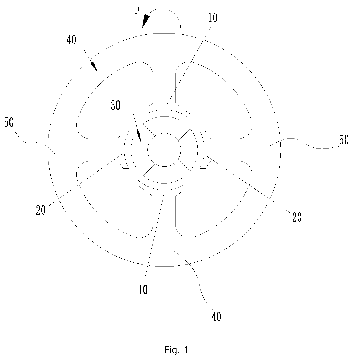
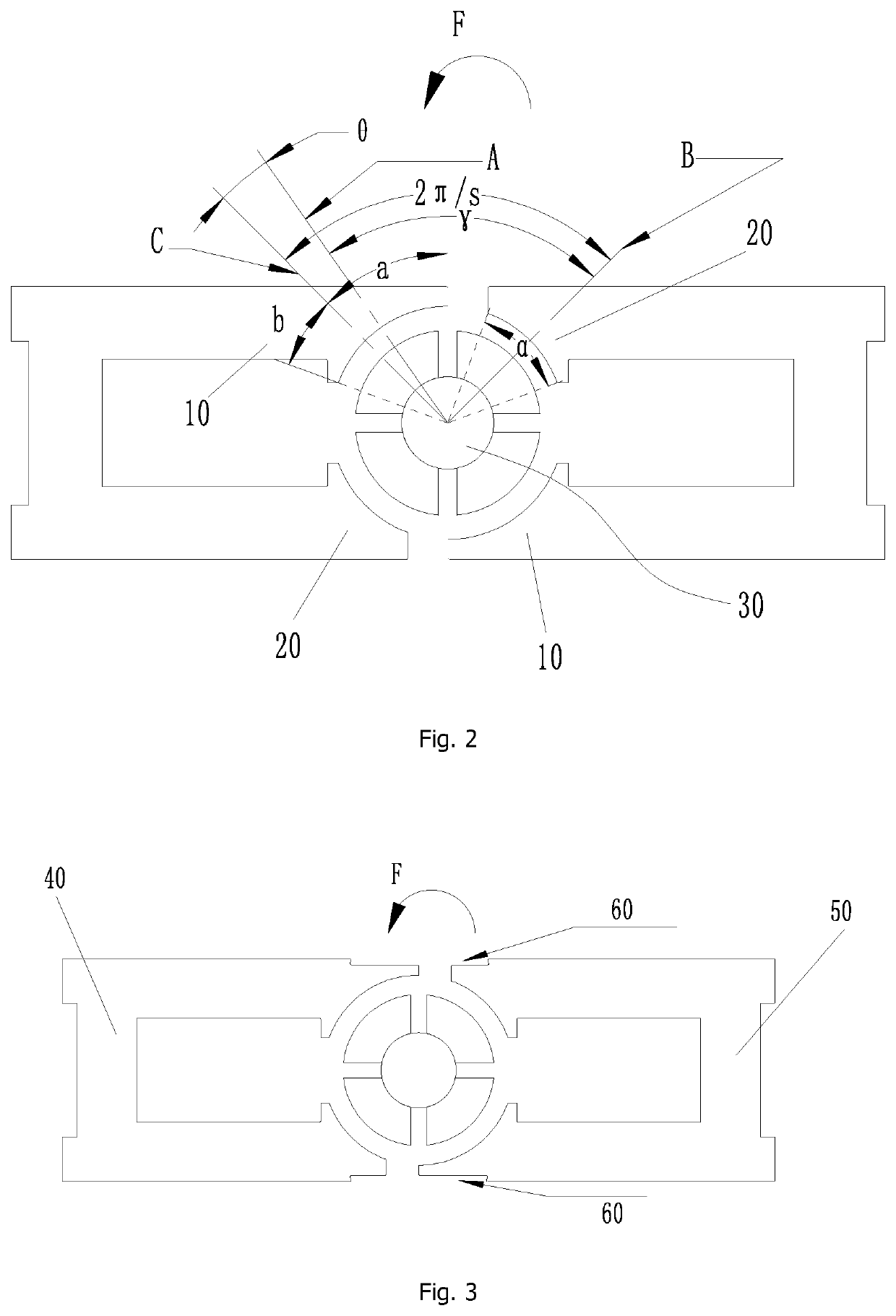
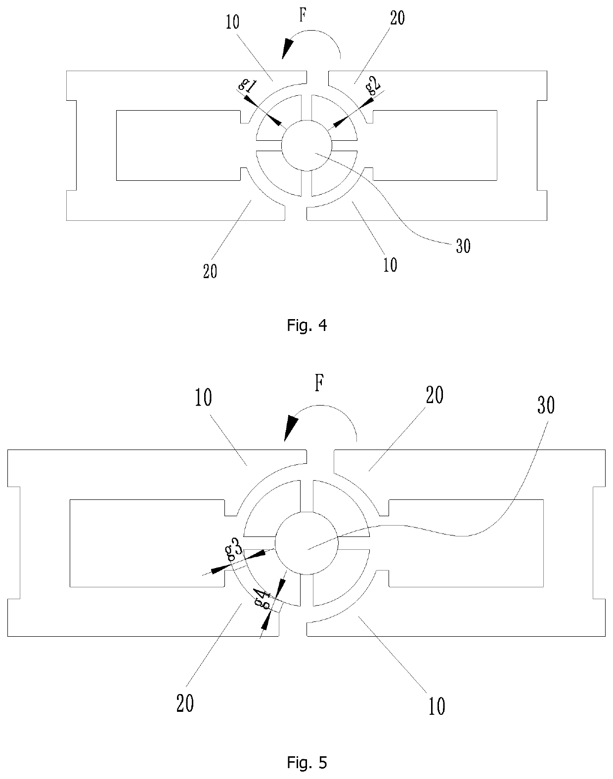
A single-phase permanent magnet synchronous motor and dust collector. The single-phase permanent magnet synchronous motor includes a plurality of stator teeth, the plurality of stator teeth include at least: a first-type and second-type stator tooth; the first-type and second-type stator teeth enclose an annular working cavity for accommodating a rotor part, where the size of a central angle corresponding to a first contour line of an end face of the first-type stator tooth facing the rotor part is different from the size of a central angle corresponding to a second contour line of an end face of the second-type stator tooth facing the rotor part The motor has a significantly reduced cogging torque, a greatly reduced torque ripple, and an obviously increased motor output torque. The single-phase permanent magnet synchronous motor is small in size, light in weight, simple in structure, convenient for large-scale manufacture and low in manufacturing cost.

Description

CROSS-REFERENCE TO RELATED APPLICATIONS[0001]This application is the United States national phase of International Application No. PCT / CN2020 / 111027 filed Aug. 25, 2020, and claims priority to Chinese patent application No. 201911253540.X, filed on Dec. 9, 2019, the disclosures of which are hereby incorporated by reference in their entirety.BACKGROUND OF THE DISCLOSURE[0002]The present disclosure relates to the technical field of motor equipment, and in particular, to a single-phase permanent magnet synchronous motor and a dust collector.DESCRIPTION OF RELATED ART[0003]A single-phase motor has a single-phase winding, which requires few switching devices in a drive main circuit, and its control system has a low hardware cost. However, a magnetic field in the single-phase motor is a pulsating magnetic field, and an electromagnetic torque of the motor has a position at a point 0. If it does not use a specific structure, a motor stop position (a point where a cogging torque is 0) coinci...

Claims


Application Information

Patent Timeline
Patent Type & Authority Applications(United States)
IPC IPC(8): H02K1/27H02K1/16H02K19/04
CPCH02K1/27H02K1/16H02K19/04H02K1/12H02K1/14H02K1/141H02K1/143H02K1/146A47L9/28H02K2213/03H02K2201/03H02K29/03H02K21/16H02K21/14
Inventor HU, YUSHENGCHEN, BINXIAO, YONGZHANG, ZHIDONGSHI, JINFEIXIAO, SHENGYULI, XIATANG, LINZHU, SHAOXUANGUI, PENGQIANSUN, HUIDING, JIATING
Owner GREE ELECTRIC APPLIANCES INC
Learn More