Fan and motor thereof

a brushless fan and motor technology, applied in the direction of dynamo-electric machines, magnetic circuit rotating parts, magnetic circuit shape/form/construction, etc., can solve the problems of deteriorating the overall performance of the motor, increasing the fabricating cost, and erroneous judgment, so as to reduce the cogging torque, increase the magnetic induction, and reduce noise

Active Publication Date: 2016-06-14
DELTA ELECTRONICS INC
View PDF29 Cites 0 Cited by
  • Summary
  • Abstract
  • Description
  • Claims
  • Application Information

AI Technical Summary

Benefits of technology

[0007]The present invention provides a motor with reduced cogging torque and reduced noise while increasing the magnetic induction between the Hall element and the magnetic assembly.
[0008]The present invention also provides a motor for obviating the problems resulting from the additional auxiliary-induction magnetic ring (e.g. increased fabricating cost, complicated fabricating process and double magnetization procedures).
[0010]In accordance with an aspect of the present invention, there is provided a motor of a brushless fan. The motor includes a base plate, a stator, a rotor, a circuit board and a Hall element. The stator is disposed on the base plate. The rotor is disposed around the stator, and includes a rotating shaft and a magnetic assembly. The rotating shaft is extended to a center part of the stator. The magnetic assembly includes plural magnets. The circuit board is arranged between the stator and the base plate and includes a Hall element. A first gap and a second gap are arranged between every two adjacent magnets. The first gap is in the vicinity of the Hall element, and opposed to the second gap. The distance of a vacant portion of the first gap is shorter than the distance of the second gap, thereby facilitating continuous and steady magnetic induction between the Hall element and the magnetic assembly.
[0011]In accordance with another aspect of the present invention, there is provided a fan. The fan includes a base plate, a stator, a rotor, a circuit board and a Hall element. The stator is disposed on the base plate. The rotor is disposed around the stator, and includes an impeller, a rotating shaft and a magnetic assembly. The rotating shaft is extended to a center part of the stator. The magnetic assembly includes plural magnets. The magnetic assembly and the stator are sheltered by the impeller. The circuit board is arranged between the stator and the base plate and includes a Hall element. A first gap and a second gap are arranged between every two adjacent magnets. The first gap is in the vicinity of the Hall element, and opposed to the second gap. The distance of a vacant portion of the first gap is shorter than the distance of the second gap, thereby facilitating continuous and steady magnetic induction between the Hall element and the magnetic assembly.

Problems solved by technology

The poor magnetic induction results in erroneous judgment and deteriorates the overall performance of the motor.
The additional auxiliary-induction magnetic ring, however, increases the fabricating cost.
Moreover, due to the size tolerance between the shaft and the auxiliary-induction magnetic ring or imprecise arrangement, a misalignment problem occurs.
In other words, the addition auxiliary-induction magnetic ring increases the fabricating cost and increases the process complexity.

Method used


Image

  • Fan and motor thereof
  • Fan and motor thereof
  • Fan and motor thereof

Examples


Embodiment Construction

[0023]The present invention will now be described more specifically with reference to the following embodiments. It is to be noted that the following descriptions of preferred embodiments of this invention are presented herein for purpose of illustration and description only. It is not intended to be exhaustive or to be limited to the precise form disclosed.

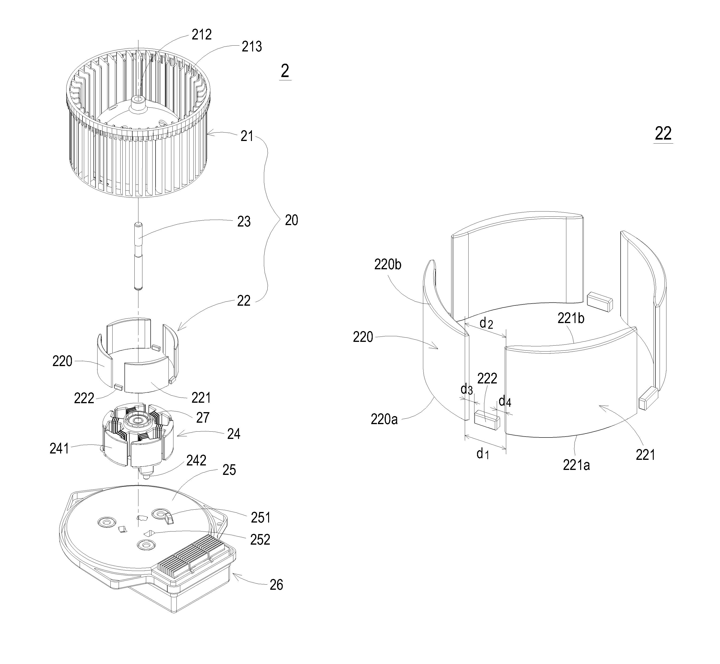
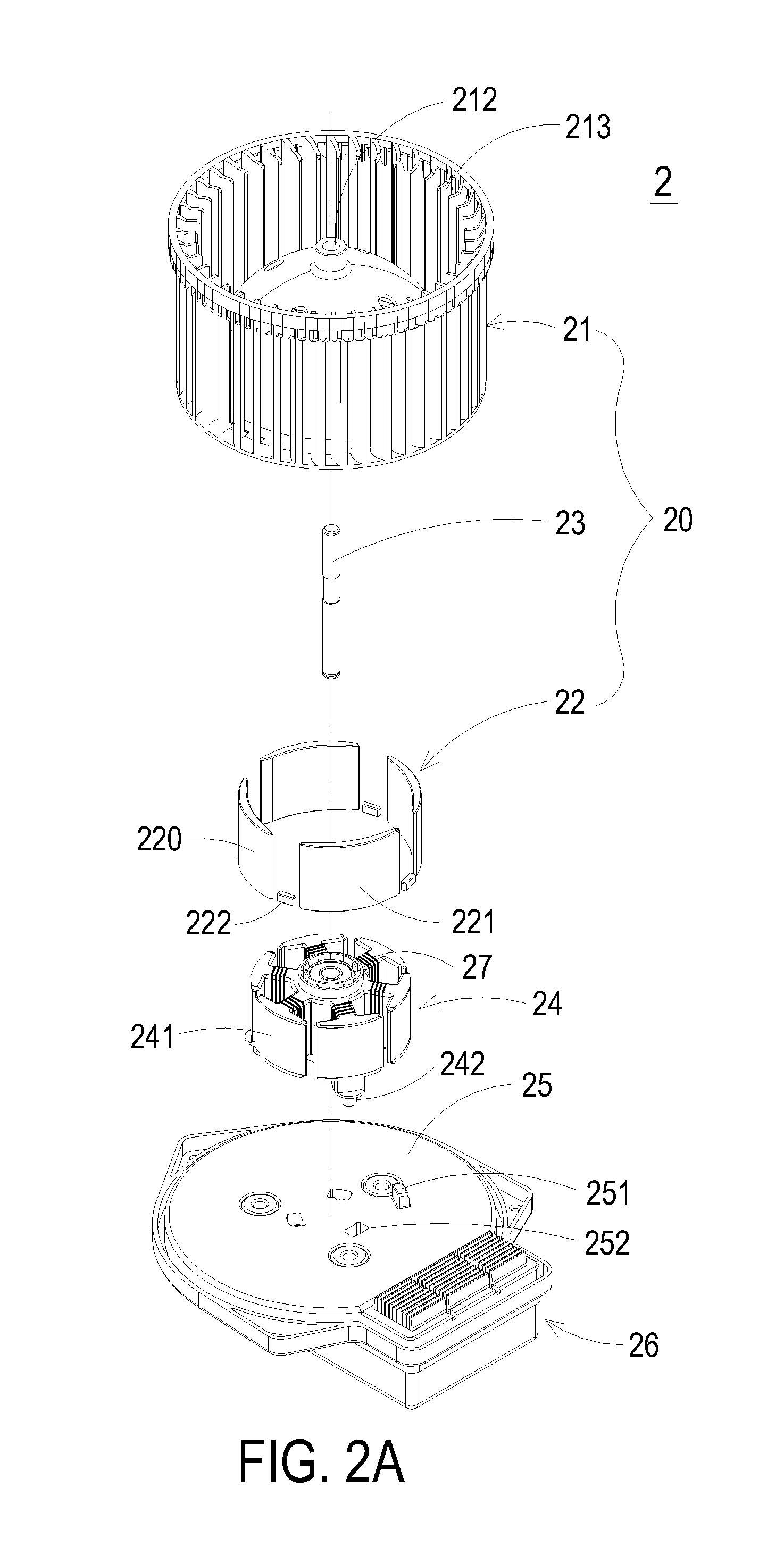
[0024]FIG. 2A is a schematic exploded view illustrating a fan according to a first embodiment of the present invention. FIG. 2B is a schematic assembled view illustrating the fan of FIG. 2A. As shown in FIG. 2A, the fan 2 includes a rotor 20, a stator 24, a circuit board 25 and a base plate 26. The rotor 20 includes an impeller 21, a magnetic assembly 22 and a rotating shaft 23. The rotating shaft 23 is extended to the center part of the stator 24. The magnetic assembly 22 includes plural magnets 220, 221, . . . , and so on. These magnets are disposed on the inner periphery of the impeller 21. A pivotal hole 212 is formed in the ...


PUM


Abstract

A motor includes a base plate, a stator, a rotor, a circuit board and a Hall element. The stator is disposed on the base plate. The rotor is disposed around the stator, and includes a rotating shaft and a magnetic assembly. The rotating shaft is extended to a center part of the stator. The magnetic assembly includes plural magnets. The circuit board is arranged between the stator and the base plate and comprises a Hall element. A first gap and a second gap are arranged between every two adjacent magnets. The first gap is in the vicinity of the Hall element, and opposed to the second gap. The distance of a vacant portion of the first gap is shorter than the distance of the second gap, thereby facilitating continuous and steady magnetic induction between the Hall element and the magnetic assembly.

Description

FIELD OF THE INVENTION[0001]The present invention relates to a motor, and more particularly to a motor of a brushless fan for facilitating a Hall element to sense continuous and steady magnetic induction.BACKGROUND OF THE INVENTION[0002]With increasing development of science and technology, the demands on heat-dissipating brushless fans become more stringent. For example, the air pressure, airflow capacity or the overall operating efficiency should comply with specified requirements. Conventionally, for reducing the noise of the operating motor of the brushless fan, the magnets of the rotor usually have chamfered edges. Due to the chamfered edges, the cogging torque of the motor is decreased, and the noise generated by the motor is reduced.[0003]A rotor of a motor of a brushless fan is disclosed in for example Taiwanese Utility Model Patent Publication No. M358465, which is entitled “Rotor structure of DC brushless motor”. FIG. 1 is a schematic view illustrating a rotor of a brushle...

Claims


Application Information

Patent Timeline
Patent Type & Authority Patents(United States)
IPC IPC(8): H02K11/00H02K29/08H02K1/27
CPCH02K1/2786H02K29/08H02K1/2791
Inventor CHIEN, HAN-ENCHEN, MENG-YUHUANG, YEN-CHUNLEE, KUN-CHOU
Owner DELTA ELECTRONICS INC
Why Eureka
Try Eureka