
Method for acquiring constant torque of electronically commutated motors

a technology of electronic commutation and constant torque, which is applied in the direction of electronic commutators, electronic commutation motor control, dc motor speed/torque control, etc., can solve the problems of high requirements, complicated mathematical models, and troublesome arithmetic, and achieve simple mathematical models and reduced pwm signal output by the microprocessor. , the effect of simple mathematical model

Active Publication Date: 2017-11-28
ZHONGSHAN BROAD OCEAN
View PDF1 Cites 1 Cited by
  • Summary
  • Abstract
  • Description
  • Claims
  • Application Information

AI Technical Summary

Benefits of technology

[0006]In view of the above-described problems, it is one objective of the invention to provide a method for acquiring a constant torque of an ECM that has simple mathematical model, simplified algorithm, low demand on the arithmetic capability on CPU, low production cost, and relatively high control accuracy.
[0011]D) comparing the target bus current Itad with a real-time bus current Ibus by the microprocessor in a closed-loop control according to the detected real-time bus current Ibus; when the target bus current value Itad is larger than the real-time bus current Ibus, increasing a duty ratio of the PWM signal output by the microprocessor; when the target bus current value Itad is smaller than the real-time bus current Ibus, reducing the duty ratio of the PWM signal; and when the target bus current value Itad is equal to the real-time bus current Ibus, stopping regulating the PWM signal, allowing the ECM to enter a working state, and repeating B) for continuing a control state of the constant torque.
[0018]1) The function of bus current Itad=C×(rpm+A) / B under the control mode of the constant torque is established by experiment means, in which, both A and B are first order functions for setting torque values T The mathematical model is simple. The microprocessor calculates a corresponding target bus current value Itad using the function of the DC bus current Itad=F(T, rpm) according to the target torque T0 and the rotational speed rpm, in which T represents the torque value output by the motor, and compares the target bus current Itad with the real-time bus current Ibus for the closed-loop control according to the detected real-time bus current Ibus. When the target bus current value Itad is larger than the real-time bus current Ibus, the duty ratio of the PWM signal output by the microprocessor is increased. When the target bus current value Itad is smaller than the real-time bus current Ibus, the duty ratio of the PWM signal output by the microprocessor is reduced. When the target bus current value Itad is equal to the real-time bus current Ibus, the regulation of the PWM signal output by the microprocessor is stopped. The number of the controlled variables is small, and the mathematical model is simple. The microprocessor, such as CPU or MCU, whose arithmetic capability is not high, can be employed so as to greatly reduce the production cost. In the meanwhile, the closed-loop control and the full measurements of the experiment means effectively ensure the control accuracy. 2) In the experiment, as long as the DC bus current and the rotational speed data corresponding to three torque points are measured, the equation for calculating the bus current Itad=C×(rpm+A) / B under the control mode of the constant torque can be acquired, thus being convenient and simple and having relatively high accuracy.

Problems solved by technology

However, the vector control mode involves complex mathematical model, troublesome arithmetic, and poses high requirements for the arithmetic capability of the CPU.
This leads to high costs.
In addition, the control mode also involves a plurality of variables and thus results in poor control accuracy.

Method used


Image

  • Method for acquiring constant torque of electronically commutated motors
  • Method for acquiring constant torque of electronically commutated motors
  • Method for acquiring constant torque of electronically commutated motors

Examples


Embodiment Construction

[0029]For further illustrating the invention, experiments detailing a method for acquiring a constant torque of an ECM are described below. It should be noted that the following examples are intended to describe and not to limit the invention.

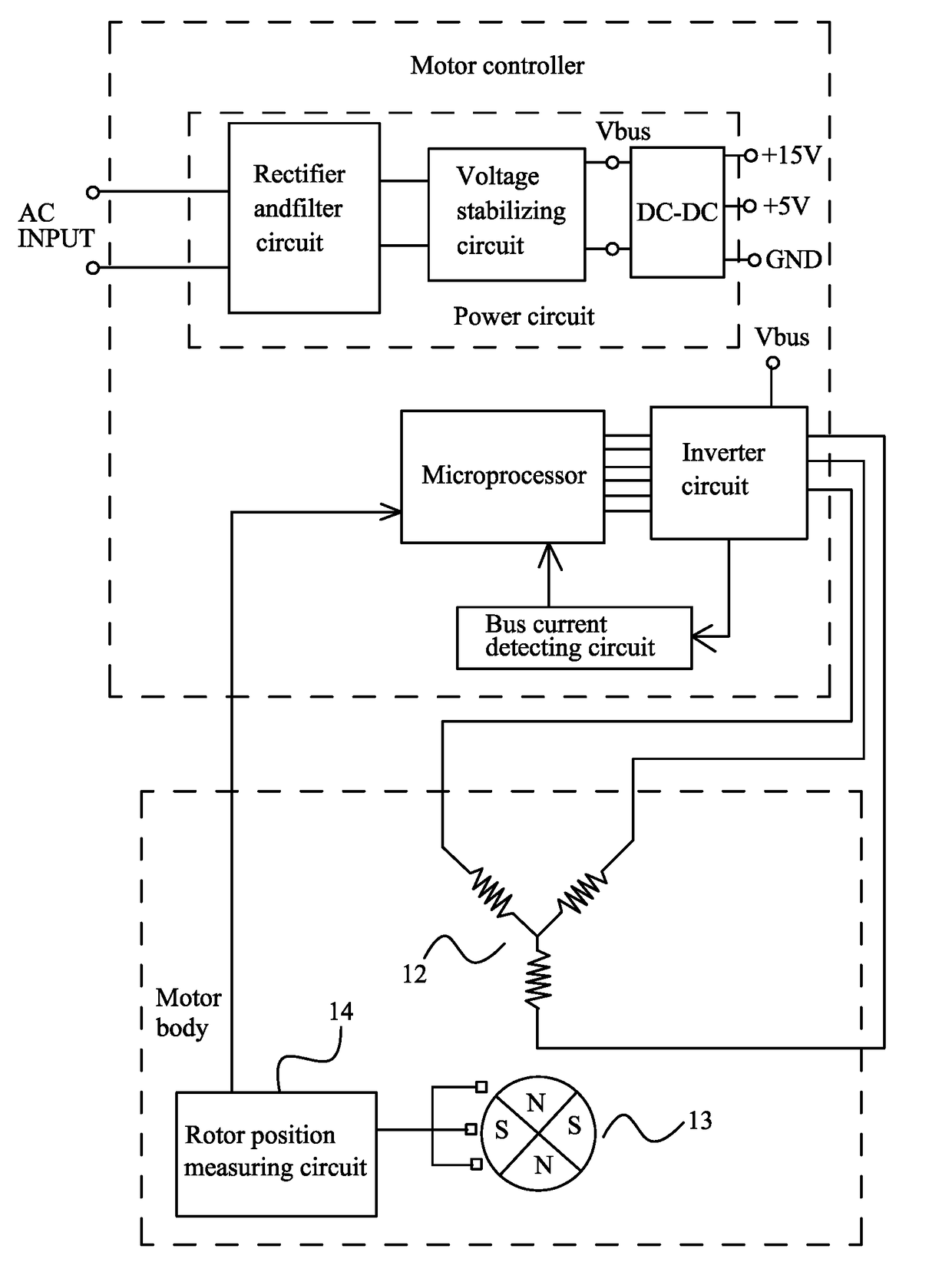
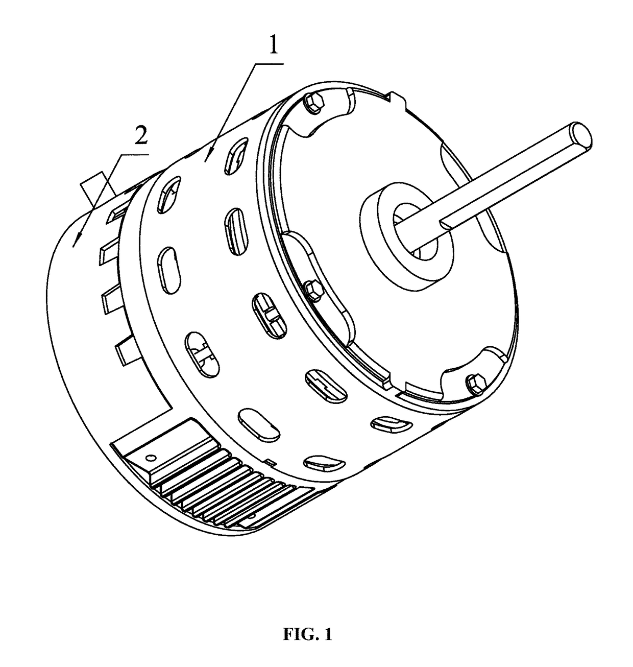
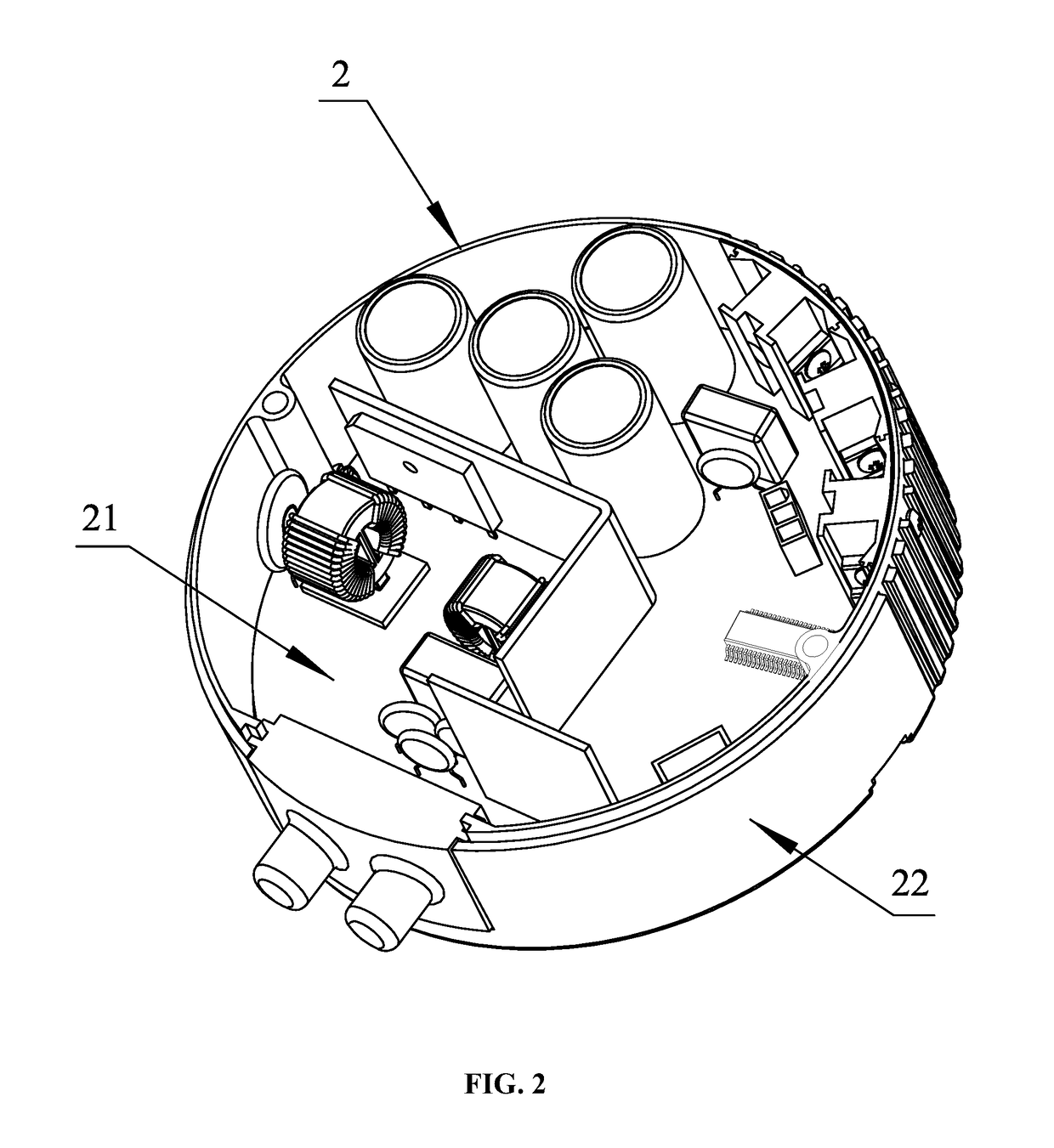
[0030]As shown in FIGS. 1-3, an ECM generally comprises a motor controller 2 and a motor body 1. The motor body 1 comprises: a stator assembly 12, a rotor assembly 13, and a housing assembly 11. The stator assembly 13 is installed on the housing assembly 11. A Hall sensor 14 is installed on the motor body 1 for detecting a rotor position. The rotor assembly 13 is nested inside or outside the stator assembly 12. The motor controller 2 comprises a control box 22 and a control circuit board 21 installed inside the control box 22. The control circuit board 21 generally comprises: a power supply circuit, a microprocessor, a bus current detecting circuit, an inverter circuit, and a rotor position measuring circuit 14 (i.e., the Hall sensor). A power ...


PUM


Abstract

A method for acquiring a constant torque of an ECM, the method including: A) acquiring a target torque value T0 input from external; B) when the motor is in a non-use state, operating the motor and acquiring an initial rotational speed rpm by the microprocessor; and when the motor is in an operating state, acquiring a current rotational speed rpm by the microprocessor; C) calculating a corresponding target bus current value Itad by the microprocessor using the function of a DC bus current Itad=F(T, rpm) according to the target torque T0 and acquired rotational speed rpm, in which T represents a torque value output by the motor; and D) comparing the target bus current Itad with a real-time bus current Ibus by the microprocessor in a closed-loop control according to the detected real-time bus current Ibus.

Description

CROSS-REFERENCE TO RELATED APPLICATIONS[0001]This application is a continuation-in-part of International Patent Application No. PCT / CN2015 / 090544 with an international filing date of Sep. 24, 2015, designating the United States, now pending, and further claims priority benefits to Chinese Patent Application No. 201510079416.1 filed Feb. 12, 2015. The contents of all of the aforementioned applications, including any intervening amendments thereto, are incorporated herein by reference. Inquiries from the public to applicants or assignees concerning this document or the related applications should be directed to: Matthias Scholl P. C., Attn.: Dr. Matthias Scholl Esq., 245 First Street, 18th Floor, Cambridge, Mass. 02142.BACKGROUND OF THE INVENTION[0002]Field of the Invention[0003]The invention relates to a method for acquiring a constant torque of an ECM.[0004]Description of the Related Art[0005]Typically, the constant torque control mode of electronically commutated motors (ECM) is a ...

Claims


Application Information

Patent Timeline
Patent Type & Authority Patents(United States)
IPC IPC(8): H02P7/00H02P23/12H02P6/16H02P23/00H02P27/08H02P6/08H02P6/15
CPCH02P6/08H02P6/085H02P6/15H02P23/0077H02P27/08H02P6/16H02P6/153
Inventor BIAN, WENQING
Owner ZHONGSHAN BROAD OCEAN
Learn More