
Barbecue grill with rotating fire receptacle

a grill and fire receptacle technology, which is applied in the field of outdoor cooking devices, can solve the problems of fats and oils burning, unfavorable cooking of food, and increased combustion of fats and oils, and achieve the effects of increasing the oxygen flow through the receptacle, increasing the combustion rate, and enhancing the convective path

Active Publication Date: 2017-12-05
KAZEROUNI BIJAN M
View PDF28 Cites 2 Cited by
  • Summary
  • Abstract
  • Description
  • Claims
  • Application Information

AI Technical Summary

Benefits of technology

[0008]The barbecue grill with a rotating fire receptacle includes a fire receptacle for receiving wood, charcoal or other combustible materials, which rotates, drawing air through vents formed through a lower wall of the receptacle, thus increasing the oxygen flow through the receptacle and both increasing the rate of combustion as well as providing an enhanced convective path for the heated combustion gases. The rotation of the fire receptacle beneath one or more cooking surfaces further allows for even cooking of the food. The barbecue grill with a rotating fire receptacle includes a vertical rod having opposed lower and upper ends, a base secured to the lower end of the vertical rod, the fire receptacle, which is rotatably mounted on the vertical rod, and a vertical support rotatably mounted on the upper end of the vertical rod. The base is adapted for supporting the vertical rod on a support surface, such as the ground or a patio, and preferably includes a plurality of legs.
[0010]Each grill tray has a front edge adapted for releasable insertion into one of the slots formed through the elongated housing of the vertical support such that the grill tray is removably supported above the fire receptacle. Each rotating basket is sized and contoured for removably receiving food items to be cooked. Each rotating basket has opposed first and second ends, with an engaging member projecting from the first end thereof and being removably received within one of the apertures formed through the elongated housing of the vertical support. A handle portion is mounted on the second end thereof for grasping and manually rotating the rotating basket. Each skewer similarly has opposed first and second ends, with the first end thereof being removably received within one of the apertures formed through the elongated housing of the vertical support. The second end thereof is adapted for gripping by the user. Multiple slots and apertures are preferably formed through the elongated housing, arranged axially, thus allowing the user to select a desired height above the fire receptacle for removable mounting of one or more of the cooking utensils.

Problems solved by technology

In a standard grill, whether one uses charcoal, gas or the like as a combustion fuel, the heat source is fixed, thus potentially leading to not only uneven cooking of the food to be prepared, but also minimizing the potential of controlled convective currents to enhance cooking of the food, as well as to control the combustion rate of the charcoal, gas or the like.
Additionally, in a conventional grill where the food is at rest with respect to the combustibles, a “flare up” is likely to occur.
Flare up occurs when fats and oils liquefy upon heating and are deposited on the heat source, causing these fats and oils to ignite.
Upon ignition of these fats and oils, an area of increased combustion occurs, potentially charring the food disposed above on the grill.
However, since more fats and oils usually drip into the new area, flare up will occur again, so that the cook must expend considerable energy in responding to the flare up to avoid burned food.

Method used


Image

  • Barbecue grill with rotating fire receptacle
  • Barbecue grill with rotating fire receptacle
  • Barbecue grill with rotating fire receptacle

Examples


Embodiment Construction

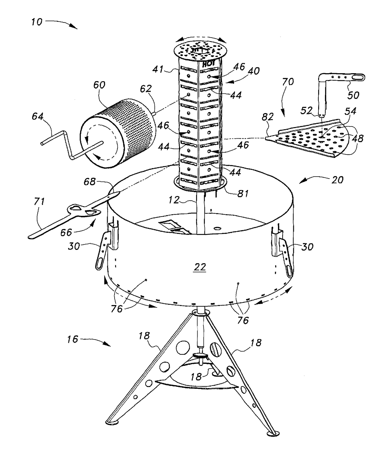
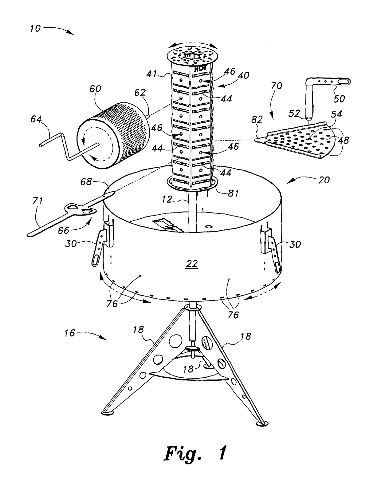
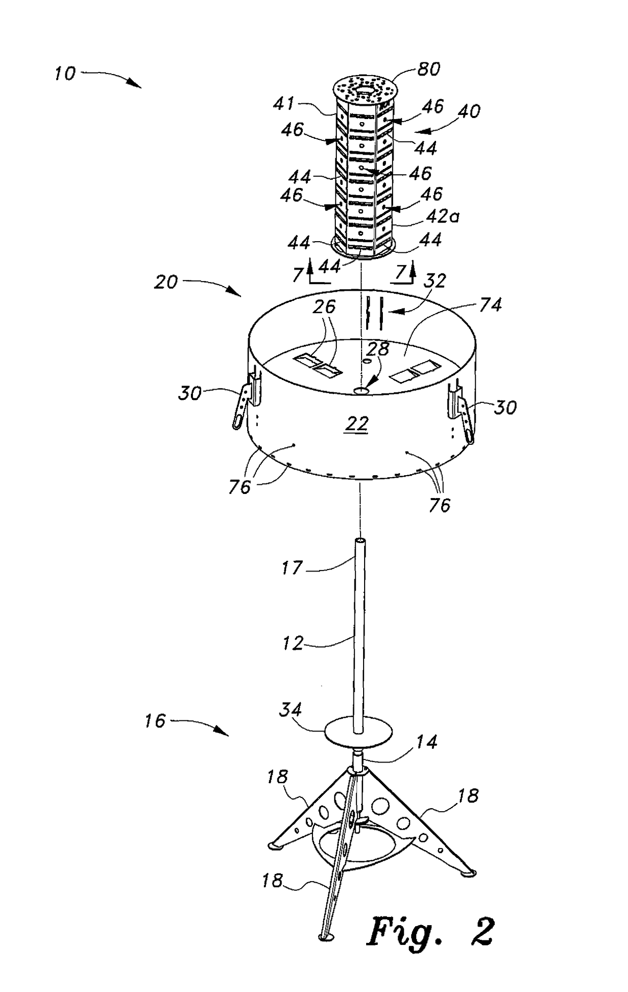
[0020]Referring now to FIGS. 1 and 2, the barbecue grill with a rotating fire receptacle 10 includes a fire receptacle 20 for receiving wood, charcoal or other combustible materials. The fire receptacle 20 is rotatable and includes vents 26 formed through a lower wall 24 of the receptacle 20 through which air may flow into the receptacle 20. Oxygen flow through the receptacle 20 increases the rate of combustion and provides an enhanced convective path for the heated combustion gases. The rotation of the fire receptacle 20 beneath one or more cooking surfaces (such as grill tray 70 in FIG. 1) further allows for even cooking of the food.

[0021]The barbecue grill with a rotating fire receptacle 10 includes a vertical rod 12 having opposed lower and upper ends 14, 17, respectively. A base 16 is secured to the lower end 14 of the vertical rod 12. The fire receptacle 20 and a vertical support 40 are rotatably mounted on the upper end 17 of the vertical rod 12. The base 16 is adapted for su...


PUM


Abstract

The barbecue grill with a rotating fire receptacle includes a fire receptacle for receiving wood, charcoal or other combustible materials, which rotates, drawing air through a plurality of air inlets, or vents, formed through a lower wall thereof, thus increasing the oxygen flow through the receptacle and both increasing the rate of combustion as well as providing an enhanced convective path for the heated combustion gases. The barbecue grill with a rotating fire receptacle includes a vertical rod having opposed lower and upper ends, a base secured to the lower end of the vertical rod, the fire receptacle, which is rotatably mounted on the vertical rod, and a vertical support rotatably mounted on the upper end of the vertical rod. The fire receptacle includes the lower wall and at least one sidewall. The fire receptacle has a central aperture and the plurality of air inlets, or vents, formed therethrough.

Description

CROSS-REFERENCE TO RELATED APPLICATION[0001]This application is a continuation-in-part of U.S. patent application Ser. No. 13 / 924,850, filed on Jun. 24, 2013, which is hereby incorporated by reference in its entirety, and which further claims the benefit of U.S. Provisional Patent Application Ser. No. 61 / 663,564, filed on Jun. 23, 2012.BACKGROUND OF THE INVENTION[0002]1. Field of the Invention[0003]The present invention relates to outdoor cooking devices, and more particularly to an outdoor barbecue grill with a rotating fire receptacle for receiving wood, charcoal or other combustible materials.[0004]2. Description of the Related Art[0005]Cooking with a barbecue grill is a popular method of preparing food, particularly in the summer months when the weather is conducive to outdoor activities. In a typical barbecue or outdoor grill, food is placed on a fixed grill surface which is mounted above a heat source, typically in the form of fire. In a standard grill, whether one uses charco...

Claims


Application Information

Patent Timeline
Patent Type & Authority Patents(United States)
IPC IPC(8): A47J37/07A47J37/04
CPCA47J37/043A47J37/0786A47J2037/0795
Inventor KAZEROUNI, BIJAN M.
Owner KAZEROUNI BIJAN M
Learn More