Silicon-air batteries

a lithium-air battery and air-cooled technology, applied in the field of energy conversion, can solve the problems of nontrivial challenges associated with a practical lithium-air cell, the consumption of al metal anodes without any usable power output, and the far-off mass production of fuel cells, etc., and achieve the effect of increasing the flow of oxygen

Active Publication Date: 2014-09-16
PENN STATE RES FOUND +1
View PDF9 Cites 1 Cited by
  • Summary
  • Abstract
  • Description
  • Claims
  • Application Information

AI Technical Summary

Benefits of technology

[0039]In some embodiments, the battery further includes a device capable of increasing the flow of oxygen therein.

Problems solved by technology

However, these fuel cells are still far from mass production due to multiple practical limitations.
However, high open circuit corrosion rates lead to the consumption of the Al metal anode without any usable power output.
Although theoretically high energy density is expected from a lithium-air cell system, nontrivial challenges associated with a practical lithium-air cell exist.
For example, Li suffers from severe corrosion in alkaline electrolytes and safety concerns are still unresolved with aqueous systems.
In addition, lithium-air cells are sensitive to anode passivation due to air / moisture contamination, the operating current density is typically very low (less than 100 μA / cm2).
Overall, the majority of these fuel cell technologies suffer from a range of drawbacks, such as size-, weight- and capacity limitations, hazardous and / or toxic components and by-products, and cost effectiveness over the entire life-cycle of the device including environmentally safe disposal.
Other obstacles associated with fuel cell development include complex electrode and cell design, catalysts poisoning and mechanical instability, high catalyst cost, low potential and slow oxidation kinetic.

Method used


Image

  • Silicon-air batteries
  • Silicon-air batteries
  • Silicon-air batteries

Examples


example 1

Silicon-Air Battery Potentiodynamic Measurements

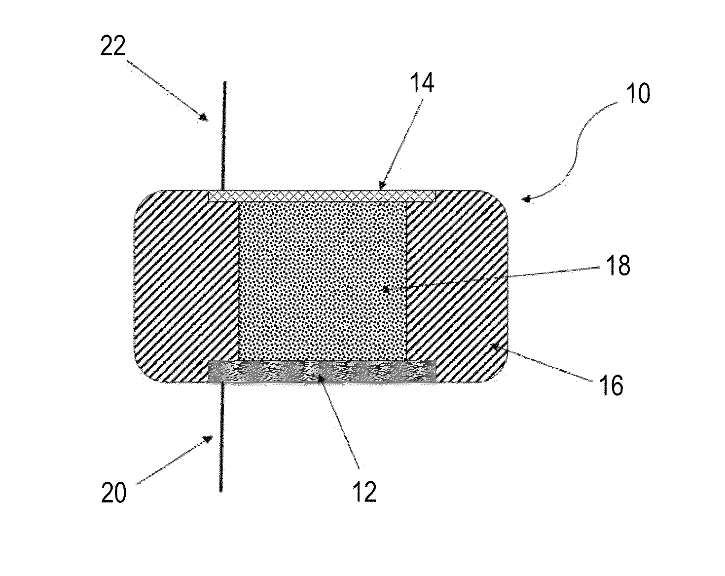
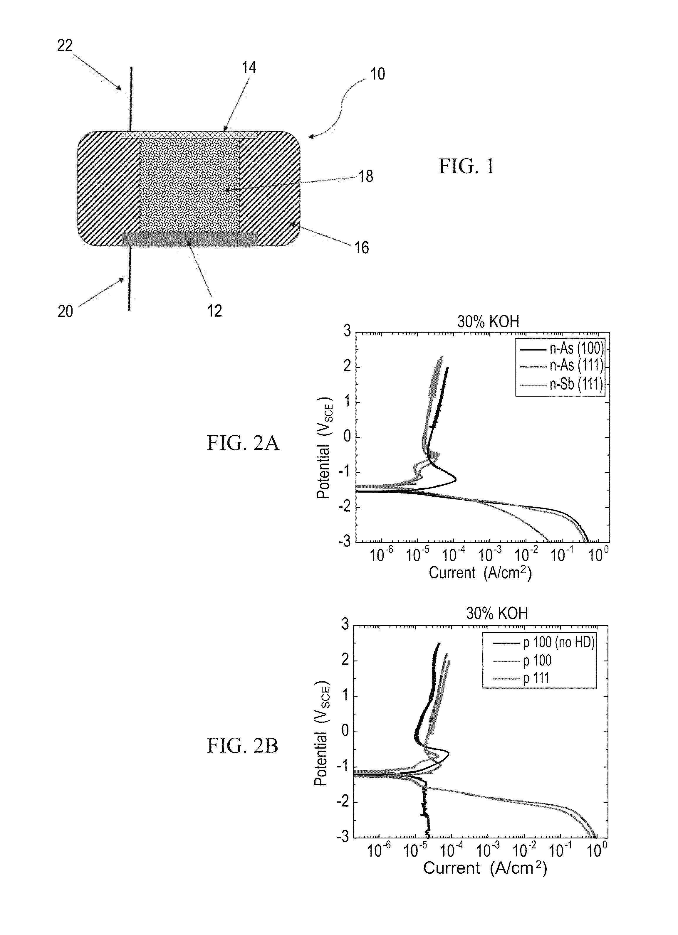
[0143]Potentiodynamic measurements were conducted using an exemplary silicon-air battery constructed according to the prototype cell presented in FIG. 1.

[0144]The electrolyte used is an alkaline solution, based on potassium hydroxide (KOH), which is a conventional electrolyte in such systems. In order to investigate the Si wafer electrochemical behavior in this environment, results from potentiodynamic experiments were obtained, with different silicon wafers and in different solution concentrations. The results for several of these cases are shown in FIGS. 2A-B.

[0145]FIGS. 2A-B present comparative potential-current curves obtained for an exemplary silicon-air battery using n-type wafers (FIG. 2A), and p-type wafers (FIG. 2B), in 30% KOH electrolyte solution, using a scan rate of 5 mV / s, wherein the black curve in FIG. 2A represents the results obtained for a Si [100] n++-doped with As, the red curve for Si [111] n++-doped with As and t...

example 2

Silicon-Air Battery Discharge Curves Measurements

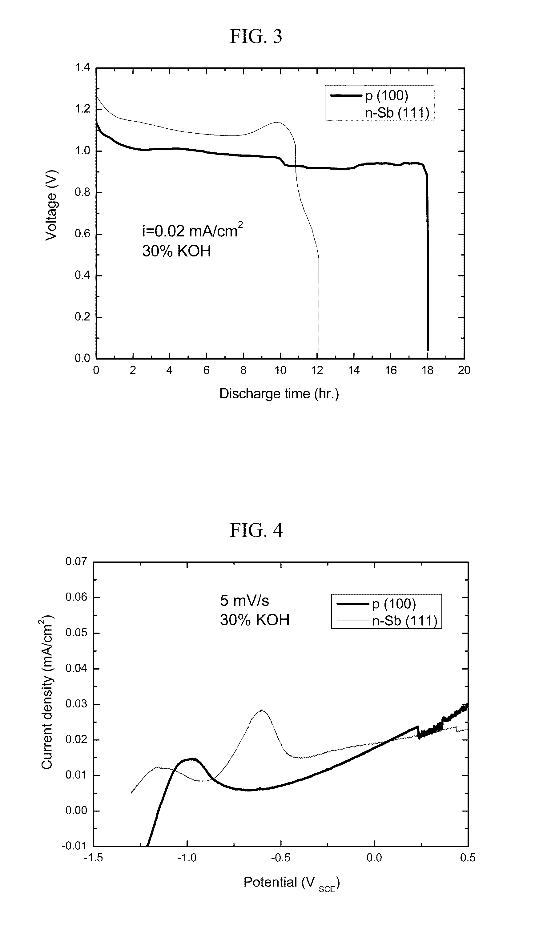
[0147]Discharge curves obtained under galvanosotatic controlled studies are shown in FIG. 3.

[0148]FIG. 3 presents a comparative plot of the discharge curves as obtained for an exemplary silicon-air battery using a silicon [100] p-type wafer (thick line) and a silicon [111] n-type wafer (thin line) in a current density of 10 μA per cm2 against an air cathode comprising carbon / catalyst composite materials pressed onto a nickel mesh.

[0149]As can be seen on FIG. 3, the silicon wafers exhibit typical discharge behavior, with a long period of a potential plateau, ending in a sharp potential drop. The battery could be discharged for a period of 12-18 hours in a current density of 20 μA per cm2, demonstrating the feasibility of a silicon-are battery according to some embodiments of the present invention.

[0150]The matching potentiodynamic measurements for the two wafers are shown in FIG. 4.

[0151]FIG. 4 presents a comparative plot of the potent...

example 3

Silicon / Iron-Air Battery System

[0153]A Fe-air battery system is known in the art, but a Si / Fe-air battery system is being studies and presented herein for the first time

[0154]The natural Fe / Si alloyed powder contains 25% silicon with an average particle size of about 20 μm.

[0155]To serve as an anode and fuel, the active Si / Fe powder was mixed with 30 wt % KOH solution (1:1) and with 0.5 wt % of the gelling agent Carbopol polymer (CAS Number 9063-87-0).

[0156]Typical discharge curve for Si / Fe-air battery system is shown in FIG. 5.

[0157]FIG. 5 presents potential-time curves for Si / Fe powder combined with the oxygen (air) cathode, in 30% KOH solution, wherein the cell was discharged in a current density of 0.1 mA per cm2, presenting a long discharge profile of above 120 hours.

[0158]As can be seen in FIG. 5, although current density discharge is sufficient, power calculations yielded low capacity values.


PUM

PropertyMeasurementUnit
operating current densityaaaaaaaaaa
working voltageaaaaaaaaaa

Abstract

Silicon-oxygen batteries comprising a silicon anode as chemical fuel, an air-cathode for dissociating oxygen, and an electrolyte, and applications using the same are provided. The silicon-batteries may utilize air for generating oxygen.

Description

RELATED APPLICATIONS[0001]This application is a National Phase of PCT Patent Application No. PCT / IL2010 / 000127 having International filing date of Feb. 11, 2010, which claims the benefit of priority of U.S. Provisional Patent Application Nos. 61 / 181,011 filed on May 26, 2009, and 61 / 156,959 filed on Mar. 3, 2009. The contents of the above applications are all incorporated herein by reference.FIELD AND BACKGROUND OF THE INVENTION[0002]The present invention, in some embodiments thereof, relates to energy conversion, and more particularly, but not exclusively, to electrochemical cell systems which utilize air and which can be utilized for forming batteries and fuel cells, and to applications of such batteries and fuel cells.[0003]The continuous search for clean, sustainable and cost-effective source of energy has pushed materials and electrochemical sciences to development of new materials and technologies for portable power sources. The prime objectives include reducing the size of th...

Claims


Application Information

Patent Timeline
Patent Type & Authority Patents(United States)
IPC IPC(8): H01M8/22H01M4/36H01M8/10H01M4/38H01M4/02H01M12/06
CPCH01M12/06H01M4/38H01M2300/0014Y02E60/128Y02E60/10
Inventor EIN-ELI, YAIRMACDONALD, DIGBY DONALD
Owner PENN STATE RES FOUND
Why Eureka
Try Eureka