Rotating machinery with adaptive bearing journals and methods of operating

a technology of bearing journals and rotating machinery, which is applied in the direction of bearings, shafts and bearings, rotary bearings, etc., can solve the problems of horizontal stiffness of bearings and reduce bearing stiffness, so as to improve the behavior of journal bearings, reduce or increase clearance, and increase damping effect.

Active Publication Date: 2017-12-05
NUOVO PIGNONE TECH SRL
View PDF10 Cites 2 Cited by
  • Summary
  • Abstract
  • Description
  • Claims
  • Application Information

AI Technical Summary

Benefits of technology

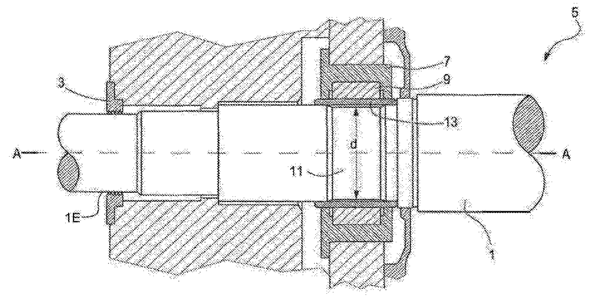
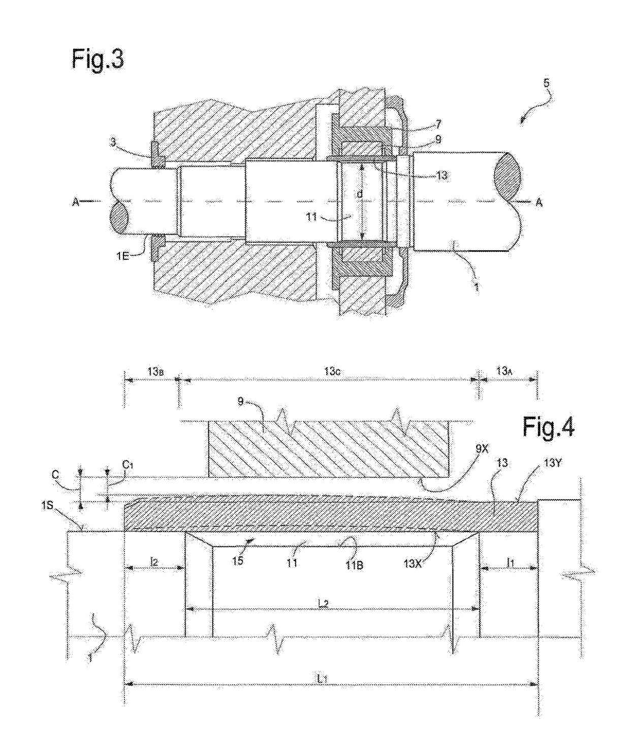
[0007]To improve the behavior of the journal bearing under different operating conditions, the journal is designed so that the outer diameter thereof can be radially deformed to selectively reduce or increase the clearance between the outer surface of the journal and the bearing surface of the journal bearing. A larger clearance is maintained at low rotation speed, to increase the damping effect and reduce amplification factors while crossing critical speeds, while at increased rotation speeds the radial dimension of the journal is increased to reduce the clearance and improve the bearing stiffness.
[0009]In some embodiments, the step of modifying the clearance comprises the steps of: increasing a rotation speed of the shaft from a first rotation speed (e.g. zero) to a second rotation speed (e.g. the rated speed of the machine), reducing the clearance while increasing the rotation speed.
[0010]In some embodiments the step of modifying the clearance comprises the steps of: reducing a rotation speed of the shaft from a second rotation speed to a first rotation speed, e.g. to zero; increasing the clearance while reducing the rotation speed. During such run down from a higher speed to a lower speed, e.g. to zero, a step can be provided of maintaining the rotation speed of the shaft at an intermediate rotation speed between the second rotation speed and the first rotation speed to cool the shaft and increase the clearance.

Problems solved by technology

Horizontal displacement resulting in a horizontal restoring force generated by the oil film results in an horizontal stiffness of the bearing.
However, larger clearances will reduce the stiffness of the bearing, which can be detrimental under normal operating conditions of the rotor.

Method used


Image

  • Rotating machinery with adaptive bearing journals and methods of operating
  • Rotating machinery with adaptive bearing journals and methods of operating
  • Rotating machinery with adaptive bearing journals and methods of operating

Examples


Embodiment Construction

[0025]The following detailed description of the exemplary embodiments refers to the accompanying drawings. The same reference numbers in different drawings identify the same or similar elements. Additionally, the drawings are not necessarily drawn to scale. Also, the following detailed description does not limit the invention. Instead, the scope of the invention is defined by the appended claims.

[0026]Reference throughout the specification to “one embodiment” or “an embodiment” or “some embodiments” means that the particular feature, structure or characteristic described in connection with an embodiment is included in at least one embodiment of the subject matter disclosed. Thus, the appearance of the phrase “in one embodiment” or “in an embodiment” or “in some embodiments” in various places throughout the specification is not necessarily referring to the same embodiment(s). Further, the particular features, structures or characteristics may be combined in any suitable manner in one...


PUM


Abstract

A method for operating a rotating machinery comprising a rotor, a rotor shaft, and at least one journal bearing supporting the rotor shaft is disclosed. The bearing comprises a bearing housing, a bearing surface in the bearing housing, a sleeve torsionally and axially fitted on the shaft, and a lubrication oil film filling a clearance between the outer surface of the sleeve and the bearing surface. The method comprises the step of modifying the clearance by modifying a radial dimension of the outer surface of the sleeve as a function of a rotation speed of the shaft.

Description

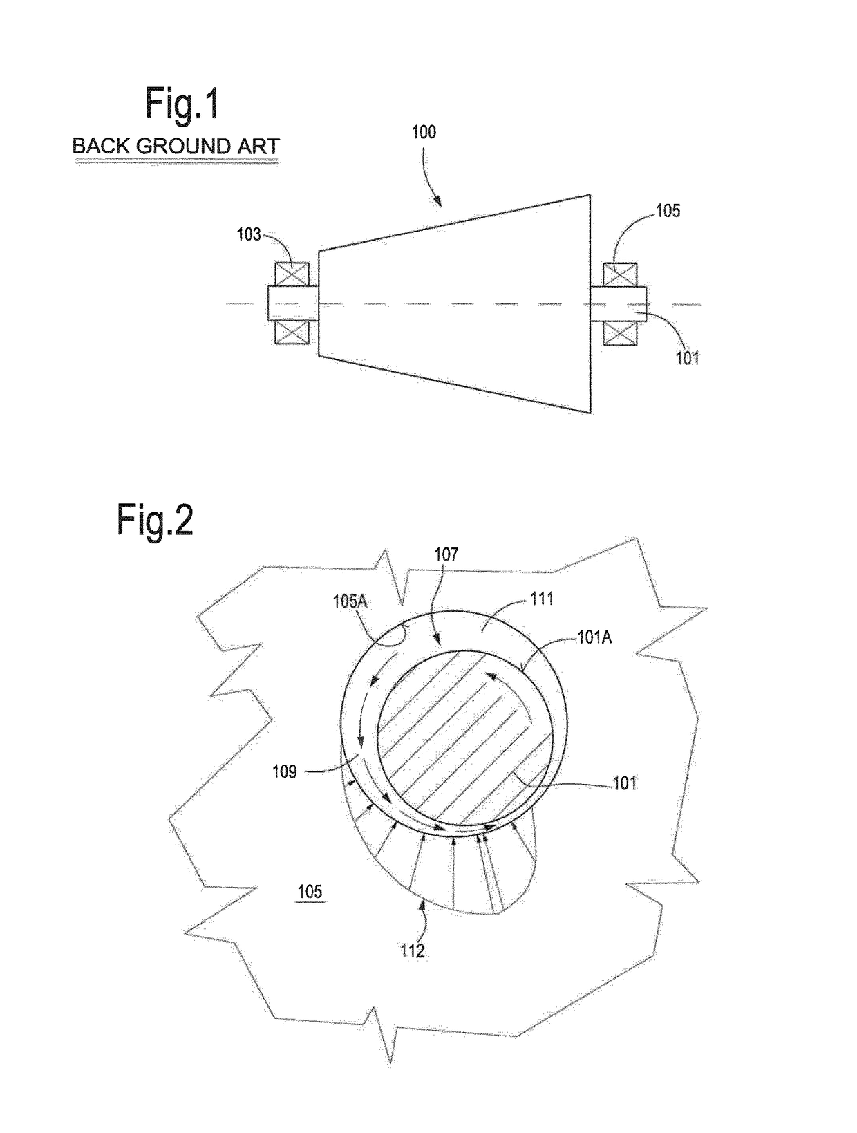
BACKGROUND[0001]Field of the Invention[0002]The subject matter disclosed herein relates to rotating machines, in particular but not exclusively to turbomachines, such as gas turbines, steam turbines, axial and centrifugal compressors. More specifically the subject matter relates to improvements concerning the bearings for the rotors of such machinery.[0003]Description of the Related Art[0004]Journal bearings or fluid film bearings are commonly used to support rotating shafts of machines rotors such as shafts of turbine rotors and compressor rotors. FIG. 1 schematically illustrates a turbomachinery rotor 100 comprising a shaft 101 supported in two end bearings 103, 105. The bearings 103, 105 can be journal bearings or so called hydrodynamic or fluid film bearings as schematically shown in FIG. 2. The shaft 101 is supported within a bearing 105, with an oil film 107 filling an annulus or clearance between an outer surface 101A of the shaft 101 and an inner bearing surface 105A of the ...

Claims


Application Information

Patent Timeline
Patent Type & Authority Patents(United States)
IPC IPC(8): F16C25/04F16C25/02F16C17/02
CPCF16C25/04F16C25/02F16C17/02F16C33/10
Inventor BALDASSARRE, LEONARDOCIANTI, ANDREAFONTANA, MICHELEBERNOCCHI, ANDREAPANARA, DANIELE
Owner NUOVO PIGNONE TECH SRL
Why Eureka
Try Eureka