
Vehicle active damper

a technology of active damper and damper, which is applied in the direction of shock absorber, vehicle sub-unit features, jet propulsion mounting, etc., can solve the problems of inability to manifest a sufficient damping effect, and the tendency for the magnitude of vibration to be amplified in the frequency band, so as to achieve sufficient attenuation of vibration components

Active Publication Date: 2017-12-05
HONDA MOTOR CO LTD
View PDF15 Cites 6 Cited by
  • Summary
  • Abstract
  • Description
  • Claims
  • Application Information

AI Technical Summary

Benefits of technology

[0009]In view of the above circumstances, the present application describes a vehicle active damper capable of securing an attenuation effect for vibration components over a wide frequency band.
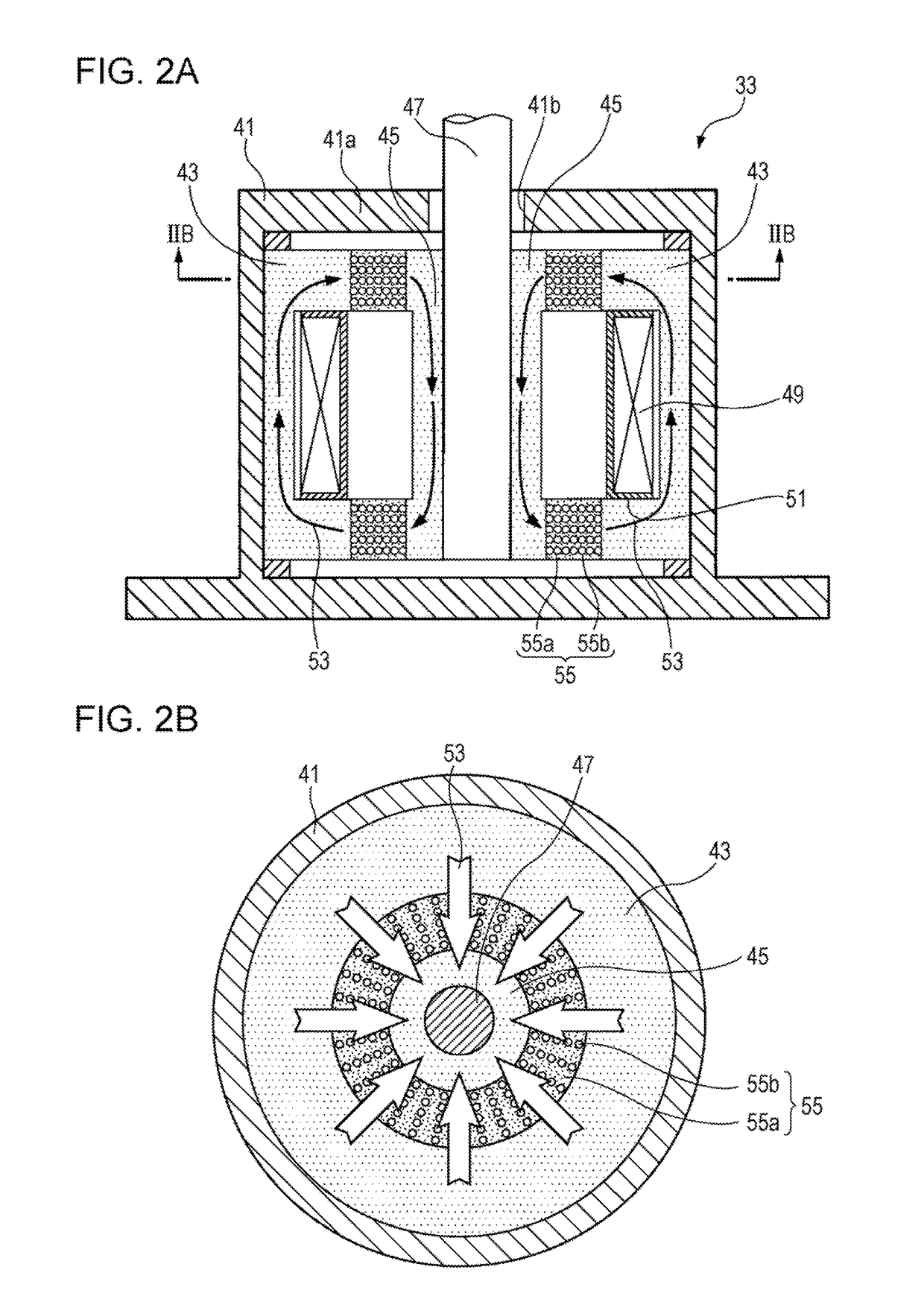
[0010]A first aspect of the present application is a vehicle active damper that actively suppresses vibrations occurring in the body of a vehicle. The vehicle active damper includes a first elastic member that is provided between a radiator and a vehicle body so as to be interposed along a substantially vertical direction, and a second elastic member that elastically couples between the vehicle body and an engine. The first elastic member is formed from an elastic modulus-variable member having an elastic modulus that varies according to the strength of an applied magnetic field. The second elastic member transmits vibrations of the engine to the vehicle body along a substantially vertical direction.
[0014]The first aspect of the embodiment employs the radiator itself as an inertial mass, and actively suppress vibrations occurring in the vehicle body by using an active dynamic damper function that widens the frequency band of damping target vibration waves using the action of the first elastic member (the variable elastic modulus member). This thereby enables an attenuation effect to be secured for vibration components over a wide frequency band.
[0017]The second aspect of the embodiment enables an anticipated effect of vibrations of the engine being effectively attenuated due to the vibrations of the engine being transmitted to the vehicle body in a substantially vertical direction, through the second elastic member that includes the extension portion and the rod portion. This thereby enables a situation to be suppressed from occurring in which vibrations occurring in the vehicle body are transmitted to inside the vehicle cabin.
[0021]The third aspect of the embodiment enables an attenuation effect to be secured for vibration components in a wider frequency band than in the first aspect or the second aspect of the embodiment, due to the first central frequency and the second central frequency being set to different frequencies from each other.
[0024]In the fourth aspect of the embodiment, setting the first central frequency to a lower frequency than the second central frequency enables sufficient attenuation of vibration components of a low frequency band, due to the active dynamic damper function manifested by the first damping control system employing the radiator itself as the inertial mass, and enables sufficient attenuation of vibration components of a frequency band higher than the low frequency band, due to the damping function manifested by the second damping control system.

Problems solved by technology

There is accordingly a concern that, as a result, it may not foe possible for a sufficient damping effect to be manifested for vibration components in the target frequency band.
Moreover, there is a tendency for the magnitude of vibrations to be amplified in the frequency bands that appear at both sides on the frequency axis either side of the first central frequency compared to cases not applied with the active dynamic damper of the first damping control system.

Method used


Image

  • Vehicle active damper
  • Vehicle active damper
  • Vehicle active damper

Examples


Embodiment Construction

[0031]Detailed explanation follows regarding a vehicle active damper 11 according to an embodiment of the present application, with reference to the drawings.

Outline Configuration of a Vehicle Applied with the Vehicle Active Damper 11 According to an Embodiment of the Present Application

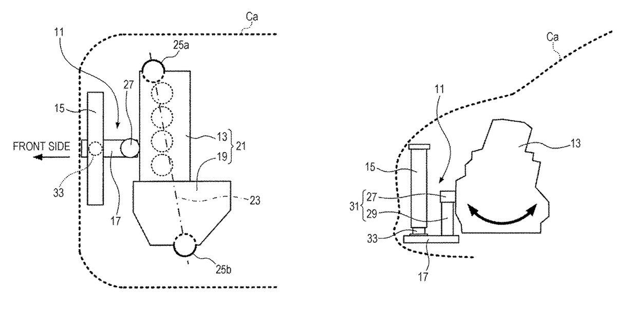
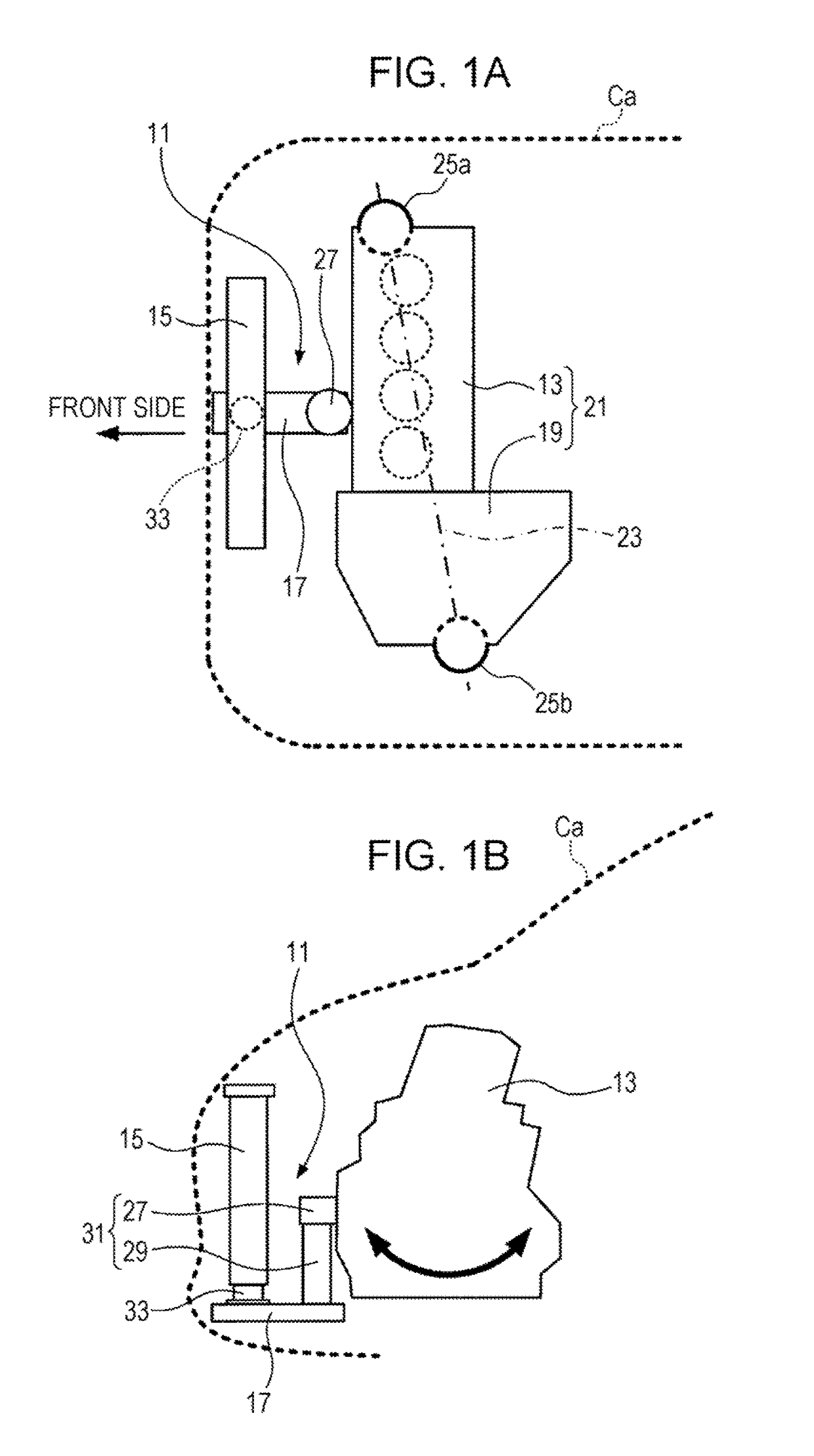
[0032]Explanation first follows regarding an outline configuration of a car Ca applied with the vehicle active damper 11 according to the present application, with reference to FIGS. 1A and 1B. FIG. 1A is a plan view schematically illustrating a positional relationship between the vehicle active damper 11, and an engine 13 and a radiator 15 provided to the car Ca. FIG. 1B is a side view schematically illustrating a positional relationship between the three elements illustrated in FIG. 1A.

[0033]The vehicle active damper 11 according to the present application has a function to actively suppress vibrations transmitted from the engine 13 to a vehicle body 17. The engine 13 illustrated in FIG. 1A is a tr...


PUM

PropertyMeasurementUnit
natural vibration frequencyaaaaaaaaaa
particle sizeaaaaaaaaaa
elastic modulusaaaaaaaaaa

Abstract

A vehicle active damper includes a damping actuator that is provided between a radiator and a vehicle body so as to be interposed in a substantially vertical direction, and a coupling member that elastically couples between the vehicle body and an engine. The damping actuator is formed from a elastic modulus-variable member having an elastic modulus that varies according to the strength of an applied magnetic field. The coupling member transmits vibrations of the engine to the vehicle body along a substantially vertical direction.

Description

CROSS REFERENCES TO RELATED APPLICATIONS[0001]The present application claims priority under 35 U.S.C. §119 to Japanese Patent Application No. 2015-097609, filed May 12, 2015, entitled “Vehicle Active Damper.” The contents of this application are incorporated herein by reference in their entirety.BACKGROUND[0002]1. Field[0003]The present disclosure relates to a vehicle active damper that actively suppresses vibrations occurring in the body of a vehicle, soon as a car.[0004]2. Description of the Related Art[0005]In a vehicle installed with a reciprocating engine, such as a car, a radiator is provided for cooling a liquid medium employed as reciprocating engine coolant. The radiator, which is a weighty object, is generally attached to a front section of the vehicle so as to readily catch the flow of air accompanying vehicle travel. Japanese Unexamined Patent Application Publication No. 57-084223 describes a vibration absorbing device that absorbs vibrations occurring in a vehicle body ...

Claims


Application Information

Patent Timeline
Patent Type & Authority Patents(United States)
IPC IPC(8): B60K5/12F16F7/10F16F7/108B60K5/04B60K11/04F16F1/36
CPCF16F7/1011B60K5/04B60K5/1208B60K5/1216F16F1/361F16F7/108B60K11/04B60Y2400/48B60Y2200/11
Inventor INOUE, TOSHIO
Owner HONDA MOTOR CO LTD
Learn More