
Illuminating device comprising quantum dot tube, backlight module, and LCD

a technology of illumination device and quantum dot tube, which is applied in the field of illumination device comprising, can solve the problems of low light availability and achieve the effect of enhancing light availability

Active Publication Date: 2017-12-05
WUHAN CHINA STAR OPTOELECTRONICS TECH CO LTD
View PDF16 Cites 0 Cited by
  • Summary
  • Abstract
  • Description
  • Claims
  • Application Information

AI Technical Summary

Benefits of technology

The present invention proposes an illuminating device that uses a QD tube, backlight module, and LCD to improve light availability. The device includes a transparent tubular encapsulation with bumps and grooves on its surfaces, and LEDs arranged in the grooves. The device also has a matching method to ensure optimal lighting performance. The technical effects of the invention include improved lighting efficiency, high light availability, and reduced light leakage.

Problems solved by technology

However, light easily leaks from gaps arranged among the LEDs and the QD tubes and from gaps arranged among the QD tubes and the LGPs, which results in low light availability.

Method used


Image

  • Illuminating device comprising quantum dot tube, backlight module, and LCD
  • Illuminating device comprising quantum dot tube, backlight module, and LCD
  • Illuminating device comprising quantum dot tube, backlight module, and LCD

Examples


Embodiment Construction

[0027]The drawings illustrate embodiments of the invention and, together with the description, serve to explain the principles of the invention.

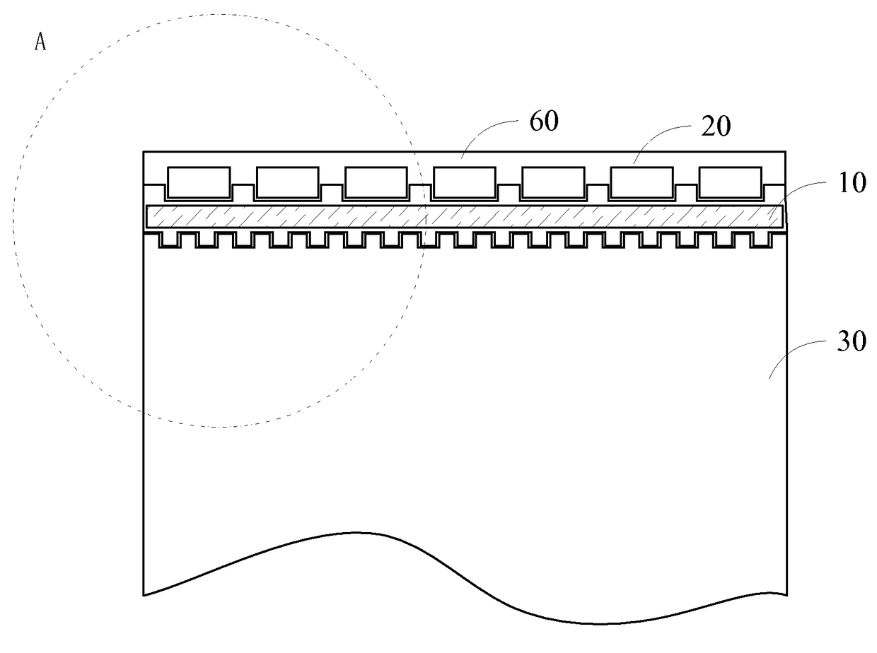
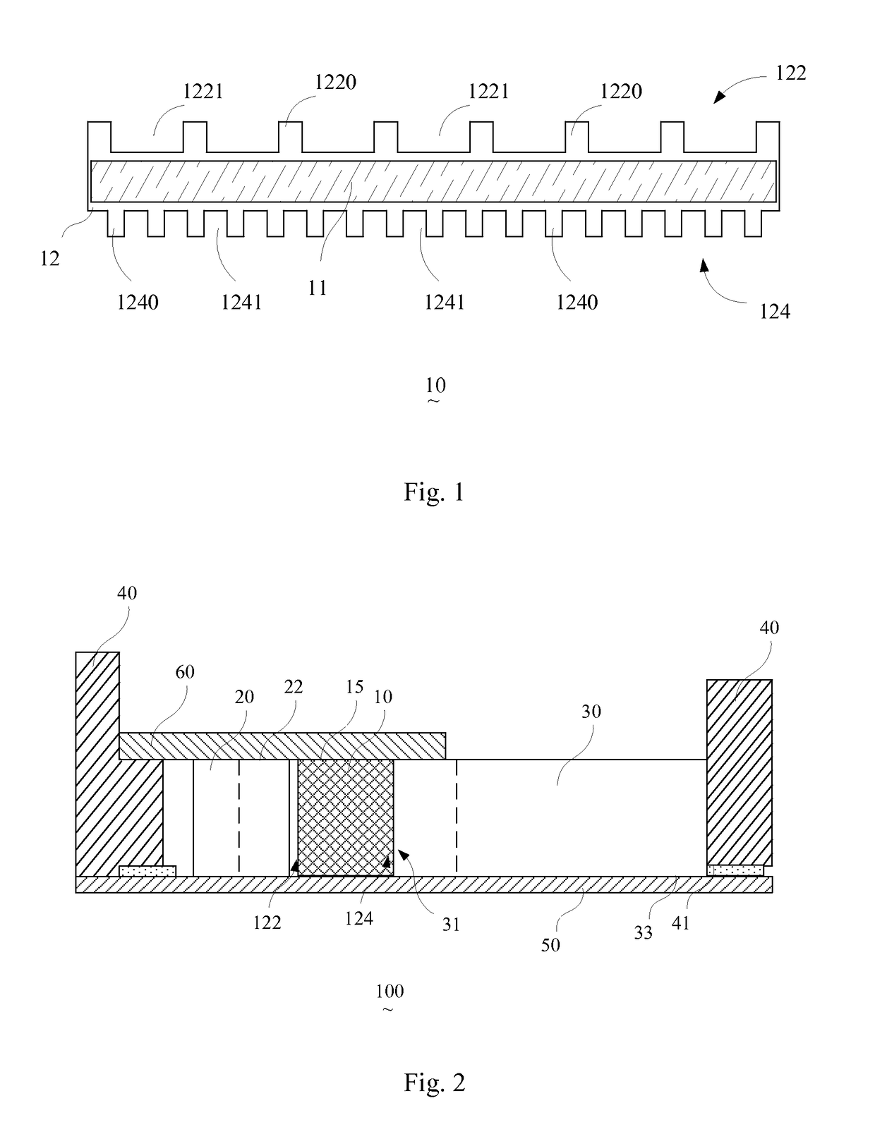
[0028]Please refer to FIG. 1. FIG. 1 is a top view of an illuminating device comprising a QD tube 10 according to one embodiment of the present invention. The illuminating device comprising a QD tube 10 comprises a QD 11 and a transparent tubular encapsulation device 12.

[0029]The QD 11 is encapsulated in the transparent tubular encapsulation device 12. The QD 11 is a nanometer particle made of Group II-VI elements and Group III-V elements. The particle diameter of the QD 11 is usually smaller than or equal to 10 nm. Because electrons and holes are controlled by quantum confinement, a continuous electronic band structure is converted into a separate electronic band structure. After being excited, the QD 11 emits fluorescence.

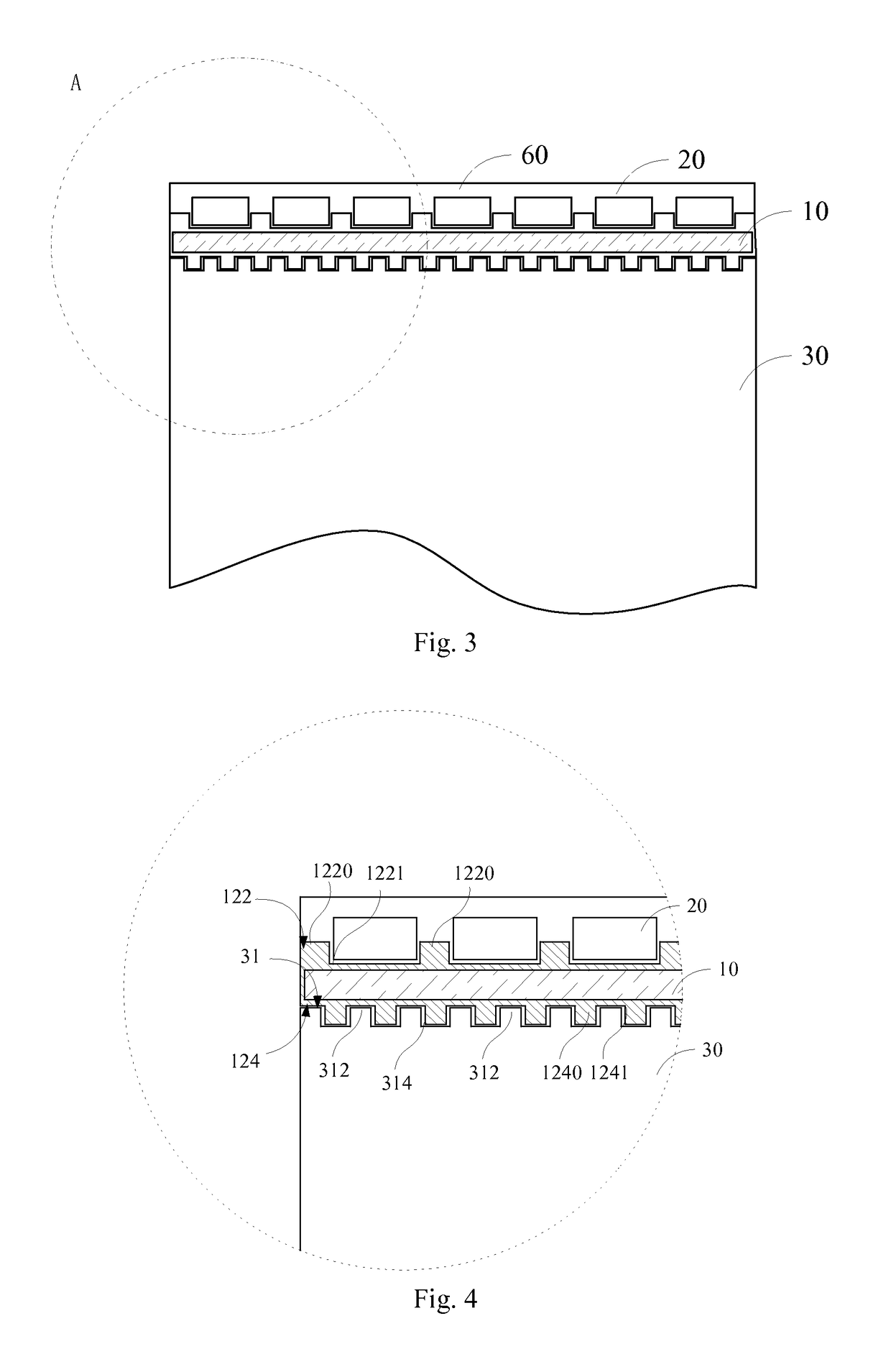
[0030]The transparent tubular encapsulation device 12 comprises a light incident surface 122 and a light emergent surfa...


PUM


Abstract

The present invention proposes an illuminating device having a quantum dot tube. The illuminating device includes: a transparent tubular encapsulation device including a light incident surface and a light emergent surface and a quantum dot. Bumps and grooves are disposed on the light incident surface and / or the emergent surface at intervals. The quantum dot is encapsulated in the transparent tubular encapsulation device. When an excitement light shines the quantum dot, the quantum dot is excited to emit light through the light incident surface. By using the illuminating device, light cannot leak from the gaps among the LEDs and the QDs and among the QDs and the LGPs, which is good for enhancing light availability. Additionally, the present invention also proposes a backlight module and a liquid crystal display using the illuminating device having the quantum dot tube.

Description

BACKGROUND OF THE INVENTION[0001]1. Field of the Invention[0002]The present invention relates to the field of liquid crystal display (LCD), and more particularly, to an illuminating device comprising a quantum dot (QD) tube, a backlight module, and an LCD.[0003]2. Description of the Prior Art[0004]After being shone by an external light source such as light emitting diodes (LEDs), QDs are excited to emit pure light with high chromaticity. The characteristic of illumination is far beyond the characteristic of illumination of phosphor powder for the LED backlight. Therefore, QD tubes where the QDs are encapsulated are widely used in the field of LCDs.[0005]Nowadays, QD tubes are usually arranged on an area between a plurality of LEDs and a plurality of light guide plates (LGPs) in the conventional LCD. However, light easily leaks from gaps arranged among the LEDs and the QD tubes and from gaps arranged among the QD tubes and the LGPs, which results in low light availability.SUMMARY OF ...

Claims


Application Information

Patent Timeline
Patent Type & Authority Patents(United States)
IPC IPC(8): F21V7/04F21V8/00
CPCG02B6/0016G02B6/005G02B6/0083G02B6/0055G02B6/009F21S2/00F21V19/00G02F1/1336H01L33/52G02F1/133615G02F1/133614
Inventor ZENG, JIE
Owner WUHAN CHINA STAR OPTOELECTRONICS TECH CO LTD
Learn More