
Direct-type backlight module and display apparatus

a backlight module and display apparatus technology, applied in the field of display technologies, can solve the problems of obvious light spots appearing on the display apparatus, increase in the cost or etc., and achieve the effects of improving uniformity, convenient manufacturing, and increasing the thickness of the backlight modul

Active Publication Date: 2015-11-05
BOE TECH GRP CO LTD +1
View PDF12 Cites 0 Cited by
  • Summary
  • Abstract
  • Description
  • Claims
  • Application Information

AI Technical Summary

Benefits of technology

The present invention provides a direct-type backlight module for a display apparatus that can achieve uniform illumination while using fewer LED lamps without increasing the light mixing distance of the backlight module. This improves the brightness and display effect of the display apparatus. The backlight module uses multiple optical fibers to direct the light emitted from the LED lamps towards the diffusion plate, transforming them into area light sources. The resulting illumination is more uniform and the display apparatus is thinner and has better display effect. In some embodiments, the light transmission openings have a circular shape which provides better uniformity of light transmission. Overall, this technology allows for improved light utilization and a thinner display apparatus.

Problems solved by technology

This leads to an increase in the cost or thickness of the backlight module.
Furthermore, when there are a fixed number of LED lamps in the backlight system, if the thickness of the backlight module is reduced, non-uniformity of the light incident on the display panel would be caused such that obvious light spots will appear on the display apparatus.

Method used


Image

  • Direct-type backlight module and display apparatus
  • Direct-type backlight module and display apparatus
  • Direct-type backlight module and display apparatus

Examples


Embodiment Construction

[0031]The technical solutions of the embodiments of the present invention will be clearly and comprehensively described as follows in combination with the figures of the embodiments of the present invention. Obviously, the embodiments described are only a part of the embodiments of the present invention, rather than all of them. All the other embodiments obtained by those ordinarily skilled in the art based on the embodiments of the present invention without spending any inventive efforts pertain to the scope claimed by the present invention.

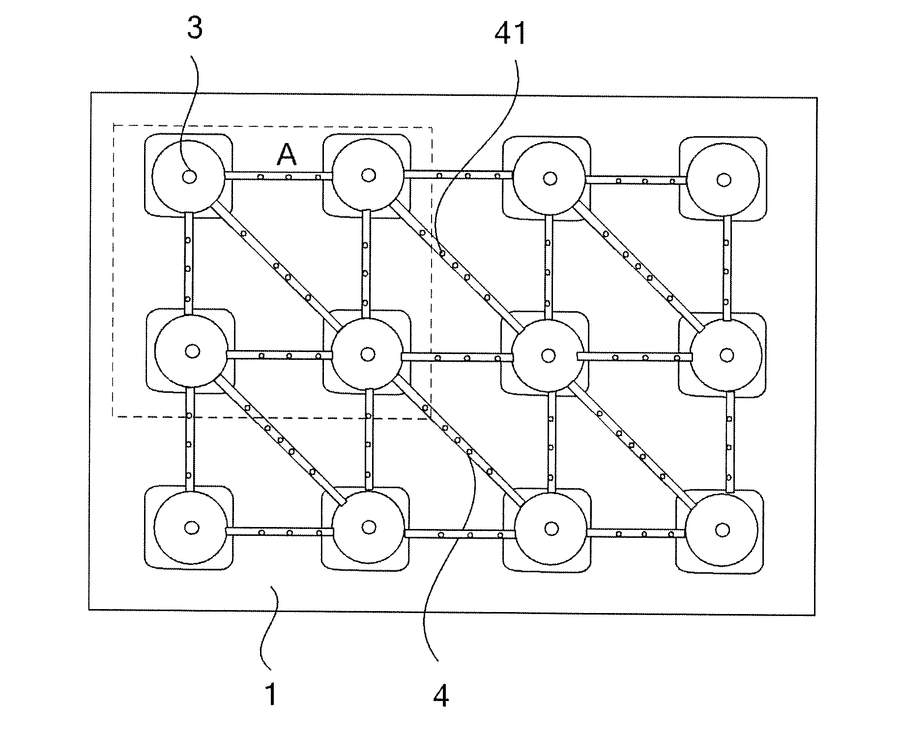
[0032]As shown in FIG. 3, which is a schematic diagram of the structure of a direct-type backlight module provided in one embodiment of the present invention. The present embodiment provides a direct-type backlight module which may comprise a backplane 1, a plurality of LED lamps 3 distributed in an array which are positioned on the backplane 1, a diffusion plate 2 above the plurality of LED lamps 3, and multiple optical fibers 4 connecting two ...


PUM

PropertyMeasurementUnit
areaaaaaaaaaaa
sizeaaaaaaaaaa
light transmissionaaaaaaaaaa

Abstract

The present disclosure provides a direct-type backlight module and a display apparatus. The direct-type backlight module may comprise: a backplane; a plurality of LED lamps distributed in an array which are positioned on the backplane; a diffusion plate above the plurality of LED lamps; and multiple optical fibers connecting two adjacent LED lamps of the plurality of LED lamps, each optical fiber being provided with a plurality of light transmission openings distributed at intervals towards the diffusion plate along its extension direction. Wherein part of light emitted from each LED lamp can be propagated along the optical fiber and transmitted to the diffusion plate via the light transmission openings. The direct-type backlight module directs part of the light emitted from the LED lamps through the plurality of light transmission openings to the diffusion plate using the optical fibers, which changes the LED lamps in the form of point light sources into area light sources. Therefore, the direct-type backlight modules provided in the present disclosure can obtain uniform illumination at the same time of reducing the number of LED lamps, without increasing the light mixing distance of the backlight modules, thereby improving light availability.

Description

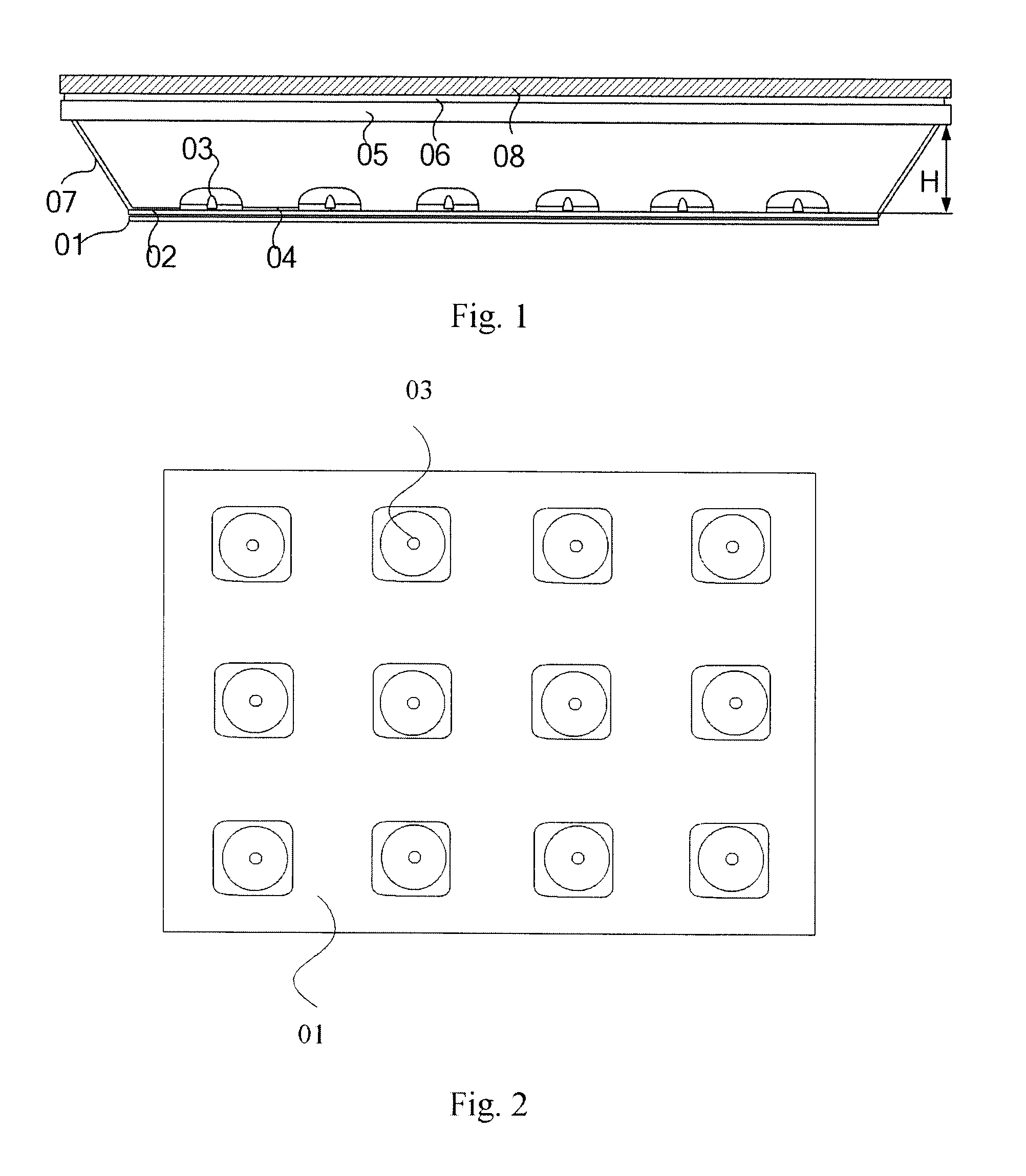
RELATED APPLICATIONS[0001]The present application claims the benefit of Chinese Patent Application No. 201410185077.0, filed May 4, 2014, the entire disclosure of which is incorporated herein by reference.FIELD OF THE INVENTION[0002]The present disclosure relates to display technologies, in particular, to a direct-type backlight module and display apparatus.BACKGROUND OF THE INVENTION[0003]Liquid crystal display apparatus is a passive light-emitting device, which does not emit light itself and requires a backlight module to provide its liquid crystal panel with a light source such that it displays images. Since the backlight module used in the liquid crystal panel has the characteristics of being light and thin and saving power, it is widely applied in display apparatuses.[0004]At present, backlight module techniques mainly used by the liquid crystal display apparatus are Cold Cathode Fluorescent Lamp (CCFL) and Light Emitting Diodes (LED).[0005]Since LED backlight module has many a...

Claims


Application Information

Patent Timeline
Patent Type & Authority Applications(United States)
IPC IPC(8): G02F1/1335F21V8/00F21Y101/00F21Y115/10
CPCG02F1/133603G02F1/133524G02F1/133606G02B6/001
Inventor ZHANG, XIAOHE, JIANMIN
Owner BOE TECH GRP CO LTD
Learn More