Pump pressure relief system

a pressure relief system and pump technology, applied in the direction of functional valve types, machines/engines, liquid fuel engines, etc., can solve the problems of significant force on the parts, serious injury or death, and the casing to fracture, so as to achieve safe dissipation and dissipate and without risk of damage or injury

Inactive Publication Date: 2017-12-12
ITT MFG ENTERPRISES LLC
View PDF12 Cites 0 Cited by
  • Summary
  • Abstract
  • Description
  • Claims
  • Application Information

AI Technical Summary

Benefits of technology

[0019]The exhaust piping arrangement may include exhaust piping configured to attach to the casing assembly, couple the rupture disc assembly in the corresponding aperture of the seal cover, and provide from the related-chamber a path for escaping vapor and solids to be directed to the external region or location where the energy can be safely dissipated without risk of damage or injury.
[0034]Mounting the rupture disc in communication with a separate chamber that does not have high velocity fluid within it eliminates the possibility for wear and premature rupture.

Problems solved by technology

Since the casing is often made of hard, brittle material (e.g. chrome iron), it is possible for the casing to fracture into multiple pieces, and for some of the pieces to be thrown significant distances with substantial force.
Were any of these pieces to make contact with a person, serious injury or death could result.
Most pumps sold today do not make any provision for relief of internal pressure should the pump or casing's ability to retain that pressure be exceeded.
Due to the pump's predetermined configuration, no piping system is easily configured or incorporated in the Model 5500 pump 40, so escaping vapor and solids cannot be directed to a safe location.
The pressure relief valve could be subject to wear and premature pressure relief.
A rupture disc may be used instead of a pressure relief valve, but it would also be mounted in direct contact with the fluid and solids and subject to premature pressure relief.
However, the pressure relief valve or rupture disc is also not directly accessible for repairs.The aforementioned Model 5500 pumps mount the pressure relief device communicating with a chamber which protects the device from direct contact with the high velocity fluid and solids.
However, no provision for piping away the exhaust is made or implemented.

Method used


Image

  • Pump pressure relief system
  • Pump pressure relief system
  • Pump pressure relief system

Examples


Embodiment Construction

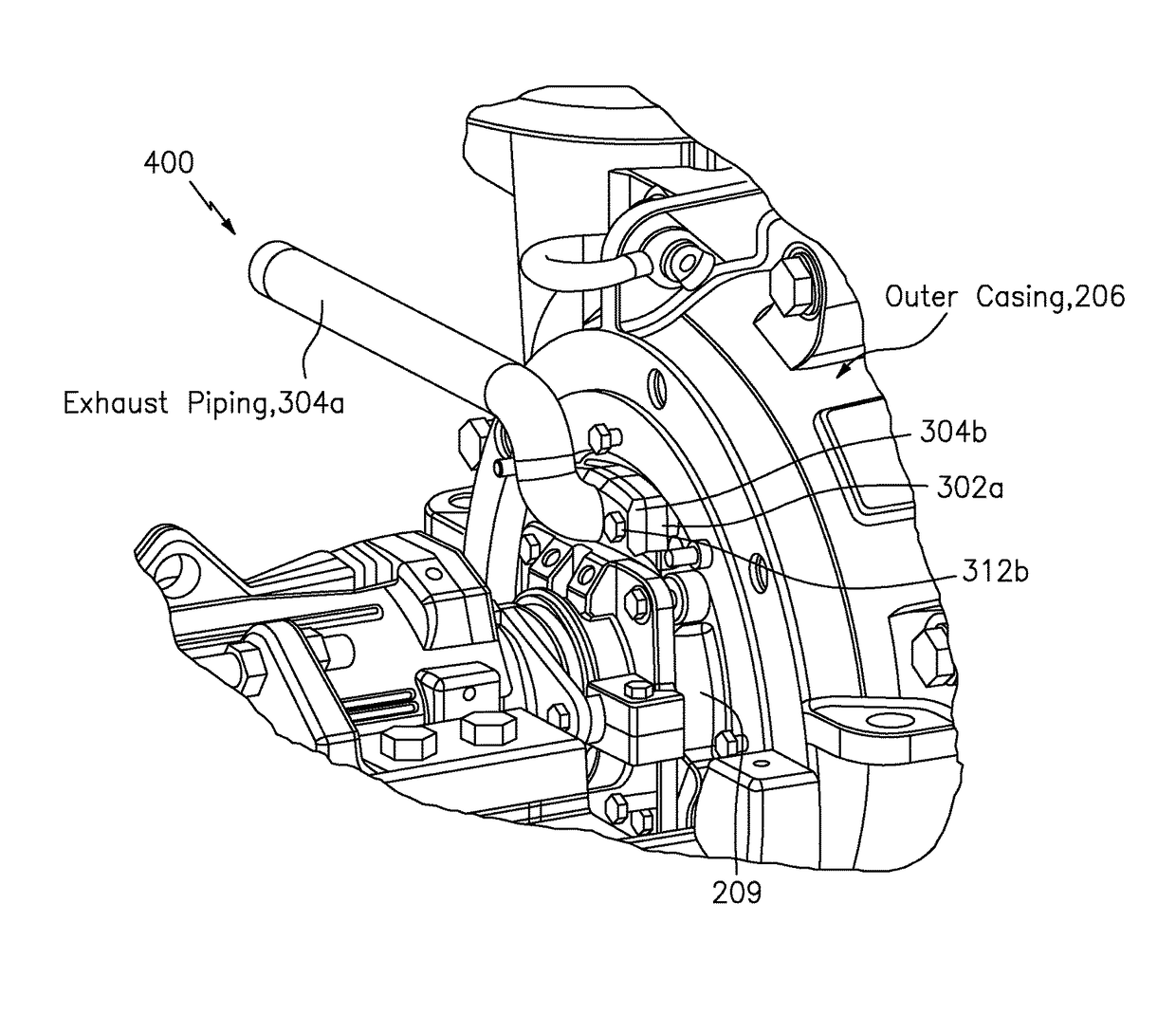
[0054]FIGS. 3, 3a and 3b show apparatus generally indicated as 100 according to some embodiments of the present invention in the form of a pump, featuring a casing assembly generally indicated as 200 and a pressure relief system generally indicated as 300 (see FIGS. 3 and 3a).

[0055]The casing assembly 200 may be configured with an inner casing 202 to form a region 204 through which high velocity fluid and solids (not shown) circulate, configured with an outer casing 206 to form a chamber 208 between the inner casing 202 and the outer casing 206 that does not have circulating therein the high velocity fluid and solids, and also configured with a seal cover 209 arranged between the inner casing 202 and the outer casing 206. The inner casing 202 may be configured with an aperture (e.g., indicated by reference numeral 202a) that, together with the seal cover 209, creates a related-chamber 208a that is in fluidic communication with the region 204 of the inner casing 202 through which hig...


PUM


Abstract

A pump features a casing assembly having a region through which high velocity fluid and solids circulate, a chamber where they do not, an aperture that allows a related-chamber to be in fluidic communication with the region, but not the circulating high velocity fluid and solids, and a corresponding aperture to allow the related-chamber to communicate with an external region outside the casing assembly; and a rupture disc received in the corresponding aperture to close the related-chamber subjects the related-chamber and the rupture disc to pressure contained within the region and to release pressure exceeding a predetermined relief pressure of the rupture disc from the related-chamber to the external region or location, and exhaust piping couple the rupture disc to provide a path for escaping vapor and solids to be directed to the external region or location where the energy can be dissipated.

Description

CROSS-REFERENCE TO RELATED APPLICATION[0001]This application claims benefit to provisional application Ser. No. 61 / 732,554, filed 3 Dec. 2012, which is hereby incorporated by reference in its entirety.BACKGROUND OF THE INVENTIONField of the Invention[0002]The present invention relates to a pump or pumping assembly, arrangement or combination; and more particularly relates to a new technique for relief of internal pressure should the maximum allowable working pressure of such a pump or pumping assembly, arrangement or combination be exceeded, e.g., including a centrifugal slurry pump.Brief Description of Related Art[0003]In certain processing facilities, it is possible to plug both the suction and discharge lines leading to a pump, especially a centrifugal slurry pump. When both lines are plugged in this fashion, and the pump continues to run, nearly all the energy transmitted by the electric motor or other source of energy input goes into heating the fluid (e.g. water) and solids (e...

Claims


Application Information

Patent Timeline
Patent Type & Authority Patents(United States)
IPC IPC(8): F16K17/16F04D29/42F04D7/04F04D15/00
CPCF04D15/0083F04D7/04F16K17/162F04D29/4286F16K17/16F04D15/0077
Inventor PADDOCK, DOUGLASPLAYFORD, MARK A.
Owner ITT MFG ENTERPRISES LLC
Why Eureka
Try Eureka