
Heat dissipating assembly

a technology of heat dissipation assembly and assembly, which is applied in the direction of lighting and heating apparatus, printed circuits, light sources, etc., can solve the problems of reducing the operable life of many led based illumination assemblies, reducing reliability and operational life, and achieving the effect of safe dissipation

Inactive Publication Date: 2016-08-09
SILESCENT LIGHTING
View PDF155 Cites 1 Cited by
  • Summary
  • Abstract
  • Description
  • Claims
  • Application Information

AI Technical Summary

Benefits of technology

The heat dissipating assembly of this patent is designed to effectively insulate LEDs from heat. It includes a compartment structure with an interior chamber that is at least partially hollow or open to contain air or other heat insulating fluid. The interior chamber is strategically located to facilitate the flow of heat from the driver assembly to the primary heat sink and then out of the illumination structure. This design ensures safe dissipation of heat and helps to maintain the LEDs at a stable temperature.

Problems solved by technology

However, certain disadvantages and problems associated with the use of LED based illumination assemblies are commonly recognized.
As such, LED illumination assemblies tend to generate a significant amount of heat during their operation, which in turn may derogatorily affect the light generated by the LED array as well as reduce the reliability and operational life thereof.
Accordingly, the operable life of many LED based illumination assemblies may be significantly reduced due to premature failure of one or more light emitting diodes associated with a light fixture or other device.
However, many known attempts do not effectively accomplish optimal heat transfer, resulting in lower operational performance and a reduced operational life as generally set forth above.

Method used


Image

  • Heat dissipating assembly
  • Heat dissipating assembly
  • Heat dissipating assembly

Examples


Embodiment Construction

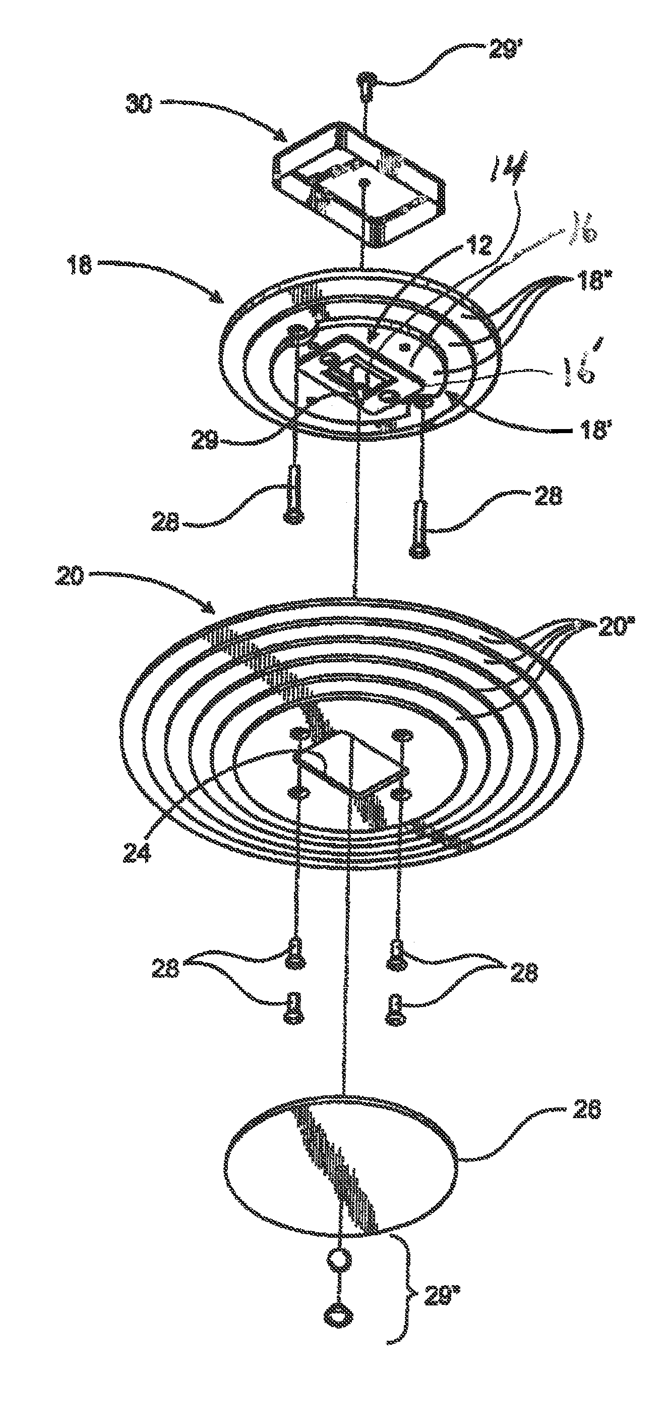
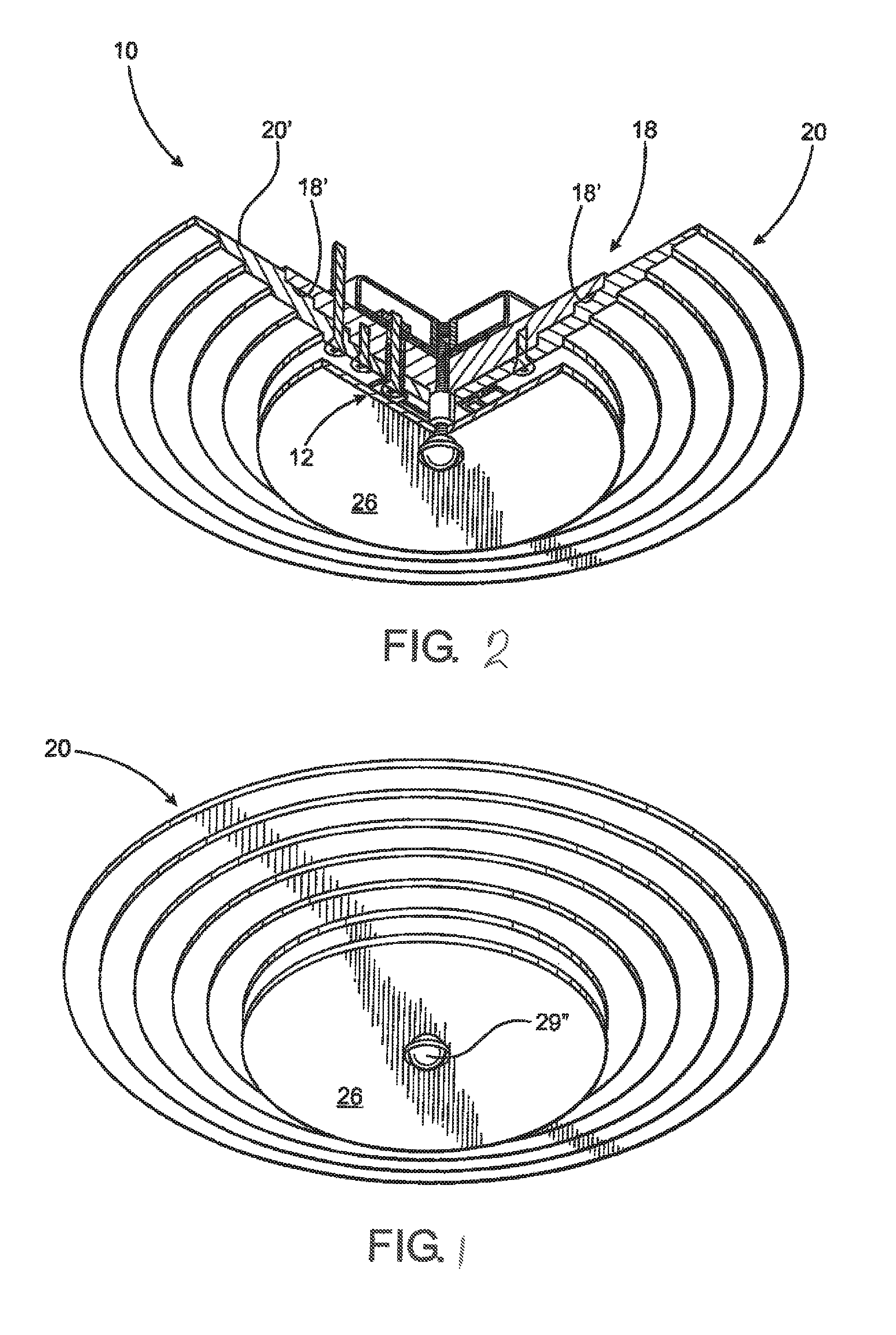
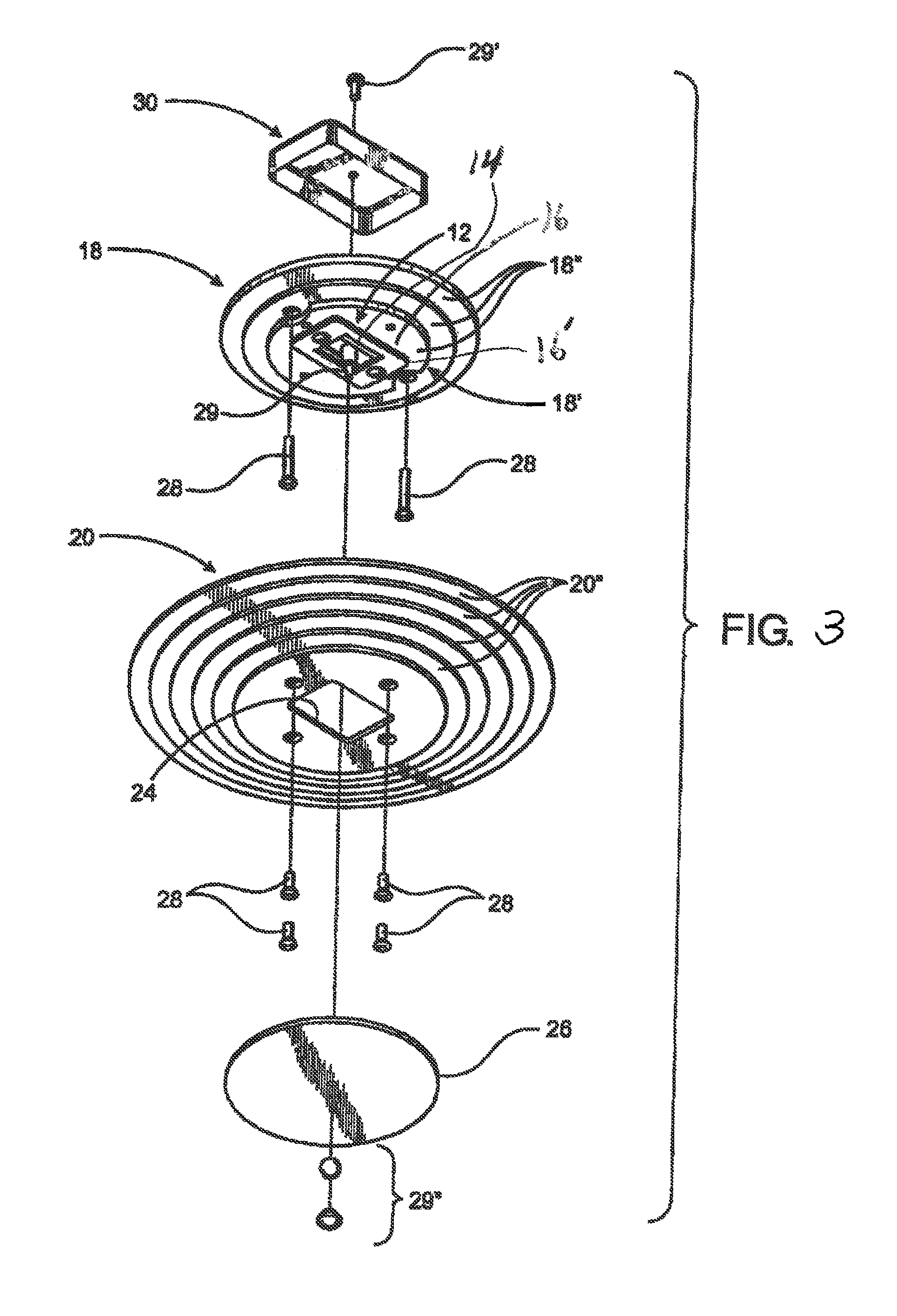
[0025]As shown in the accompanying drawings, the present invention is directed to a heat dissipating assembly, generally indicated as 100, as schematically represented in FIG. 4. However, for the purpose of clarity and by way of example, FIGS. 1-3 disclose a representative light fixture generally indicated as 10, with which the heat dissipating assembly 100 may be used. It is emphasized that the heat dissipating assembly 100 may vary in structure and operation from the light fixture 10 of FIGS. 1-3, as pointed out in greater detail hereinafter, without departing from the intended spirit and scope of the present invention.

[0026]Accordingly, the light fixture 10 is of the type which may be installed in any of a variety of commercial, domestic or other sites and is decorative as well as functional to effectively illuminate a given area or space in the vicinity of the installed location. More specifically, the light fixture 10 includes an illumination structure generally indicated as 12...


PUM


Abstract

An assembly for the dissipation of heat from an illumination structure of the type which includes one or more LEDs and a driver assembly operatively connected to the one or more LEDs. A primary heat sink is disposed in heat transferring relation to the components of a remainder of the illumination structure. A mount, also formed of a heat conductive material, is disposed in supporting or connected relation to the driver and in heat transferring relation to the primary heat sink. A compartment structure includes a hollow interior chamber, having heat insulating fluid disposed therein, and disposed in adjacent and / or aligned relation with the one LED so as to insulate it from heat generated by the driver assembly and other components of the light structure. The mount, primary heat sink and compartment structure are cooperatively disposed so as to define a flow path of heat away from the one or more LEDs to an area where it is dissipated exteriorly of the illumination structure.

Description

BACKGROUND OF THE INVENTION[0001]1. Field of the Invention[0002]This invention is directed to a heat dissipation assembly for an illumination structure of the type which includes at least one LED and a driver operatively connected to the LED. A compartment structure, including an interior chamber having heat insulating fluid disposed therein, is disposed in predetermined adjacent and / or aligned relation to the LED and the driver assembly and / or other heat generating components to effectively restrict the exposure of the LED to heat.[0003]2. Description of the Related Art[0004]Various types of illumination assemblies which incorporate light emitting diodes (LED) as the light generating component have become increasingly popular in recent years. Such an increase in popularity is due, at least in part, to their overall efficiency as well as the ability to define various lighting arrays readily adaptable to numerous practical installations or applications.[0005]Accordingly, LEDs are kno...

Claims


Application Information

Patent Timeline
Patent Type & Authority Patents(United States)
IPC IPC(8): F21V29/00
CPCH05K1/00F21V29/10F21V29/503F21V29/508F21V29/85F21Y2105/10F21Y2115/10
Inventor SUTHERLAND, MARKSUAREZ, JOSE
Owner SILESCENT LIGHTING
Learn More