
Gaiter

a technology for lubricating joints and gaiters, which is applied in the direction of tyre parts, tyre measurements, yielding couplings, etc., can solve the problems of not desirable, pressurize and inflate the gaiter

Active Publication Date: 2017-12-19
JAGUAR LAND ROVER LTD
View PDF13 Cites 4 Cited by
  • Summary
  • Abstract
  • Description
  • Claims
  • Application Information

AI Technical Summary

Benefits of technology

The gaiter effectively isolates gas flow from the lubricated joint, preventing pressure equalization and maintaining the integrity of the lubricant, while allowing compressed air to pass through without causing deformation or constriction, thus ensuring efficient tire inflation and deflation operations.

Problems solved by technology

Air supplied through the CV joint to inflate or deflate the tyre may leak into the CV joint enclosure delimited by the gaiter and can thus pressurize and inflate the gaiter.
This is not desirable, and vented gaiters have been proposed to equalise pressure.

Method used


Image

  • Gaiter
  • Gaiter

Examples


Embodiment Construction

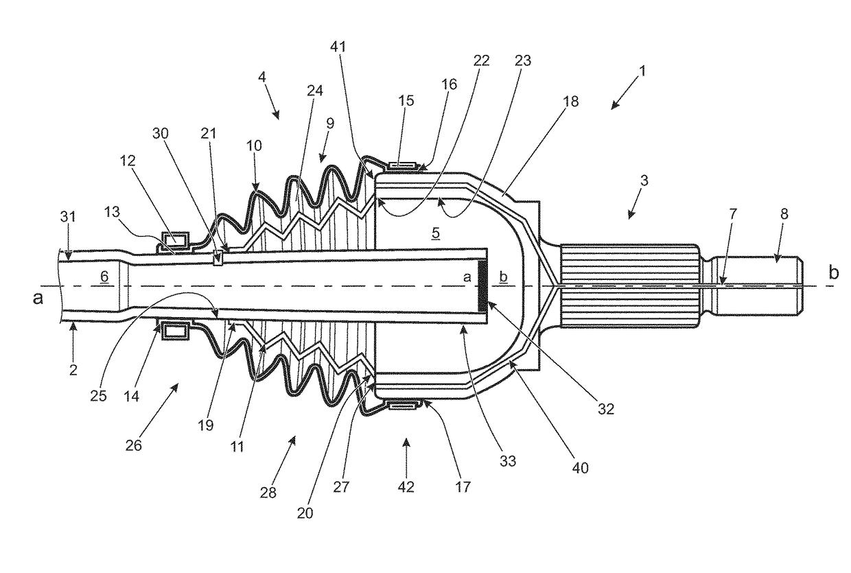
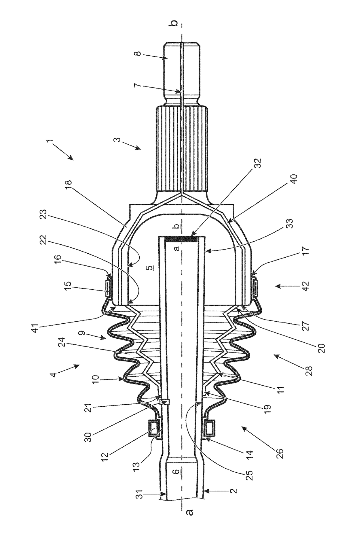
[0049]A constant velocity (CV) joint 1 adapted for internal passage of compressed air will now be described with reference to the drawings. The CV joint 1 is part of a vehicle central tyre inflation system (CTIS). The CTIS allows a driver to inflate a tyre mounted on a wheel connected to the CV joint 1 from on-board the vehicle. The CTIS, tyre and wheel are not shown in the drawings and are of the type described in the co-pending patent application number GB1313622.1 filed on 30 Jul. 2013, the contents of which are incorporated herein in their entirety by reference.

[0050]With reference to FIG. 1, the CV joint 1 is formed by a hollow driveshaft 2 coupled to a hollow wheel stub axle 3. A CV joint gaiter 4 creates a CV joint enclosure 5 for receiving CV joint inner components (bearings, cage, any spacers etc.) and a lubricant, such as grease, for lubricating said inner components. The inner components of the CV joint 1, and the lubricant, are not shown in FIG. 1 for clarity of represen...


PUM


Abstract

A gaiter (4) for a lubricated joint (1) comprises a sidewall structure (9) defining an enclosure (5) for receiving a lubricant and a passageway (24) for conveying a gas. In use, the passageway (12) conveys gas in isolation from said enclosure (5). Gaiters (4) in accordance with the invention find application in vehicle central tire inflation systems (CTIS).

Description

RELATED APPLICATIONS[0001]This application is a 35 U.S.C. §371 national stage application of PCT Application No. PCT / EP2014 / 069500, filed on Sep. 12, 2014, which claims priority from Great Britain Patent Application No. 1316250.8 filed on Sep. 12, 2013, the contents of which are incorporated herein by reference in their entireties. The above-referenced PCT International Application was published in the English language as International Publication No. WO 2015 / 036542 A2 on Mar. 19, 2015.TECHNICAL FIELD[0002]The present disclosure relates to a gaiter for a lubricated joint. In particular, but not exclusively, aspects of the present invention relate to a gaiter for a lubricated joint for a central tyre inflation system (CTIS); to a hollow vehicle axle shaft; to a hollow wheel stub axle; to a vehicle axle assembly; to an articulated joint; to a CTIS; and to a vehicle.BACKGROUND OF THE INVENTION[0003]The present invention was conceived in the context of on-board central tyre inflation sy...

Claims


Application Information

Patent Timeline
Patent Type & Authority Patents(United States)
IPC IPC(8): F16J3/04B60C23/00F16D3/223F16D3/84
CPCF16J3/046B60C23/003F16J3/041F16D3/845F16D2003/846F16D3/223B60C23/00336B60C23/00
Inventor DUNNING, EMMA-CLAIREHOARE, EDWARDDODU, MAELLELAANEMETS, LAUR
Owner JAGUAR LAND ROVER LTD
Learn More