Artificial light and evacuated tube boiler

a technology of evacuated tube and artificial light, which is applied in the field of boilers, can solve the problems of increasing gas and electricity costs, affecting the efficiency of each of these systems, and affecting the efficiency of each system,

Inactive Publication Date: 2018-01-02
DUNN BRIAN
View PDF11 Cites 1 Cited by
  • Summary
  • Abstract
  • Description
  • Claims
  • Application Information

AI Technical Summary

Problems solved by technology

With the cost of gas and electricity continuously increasing, this method of heating has become expensive to operate.
Each of these systems suffers from various inefficacies.
In particular, these systems require a substantial framework to house the apparatus which does not aid in transforming electrical energy into heat.
These systems are expensive to manufacture and install.
Whereas this can be an inexpensive way to produce heated water, direct solar heating systems suffer from several drawbacks.
In addition, these systems require large panels or surfaces exposed to the sun that are external to the dwelling and are inconvenient install and difficult to maintain.
These types of solar heaters are better suited for heating water for residential use, as it may be difficult to reach and maintain the temperatures required for a hydronic heating system without the extensive use of large solar panels.
All forms of solar energy systems are ultimately tied to the availability of the sun, which is unavailable at night, may be greatly diminished in bad weather.

Method used


Image

  • Artificial light and evacuated tube boiler
  • Artificial light and evacuated tube boiler
  • Artificial light and evacuated tube boiler

Examples


Embodiment Construction

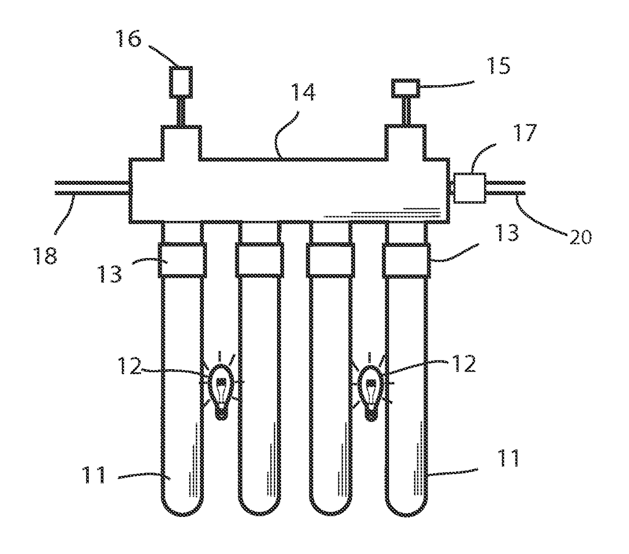
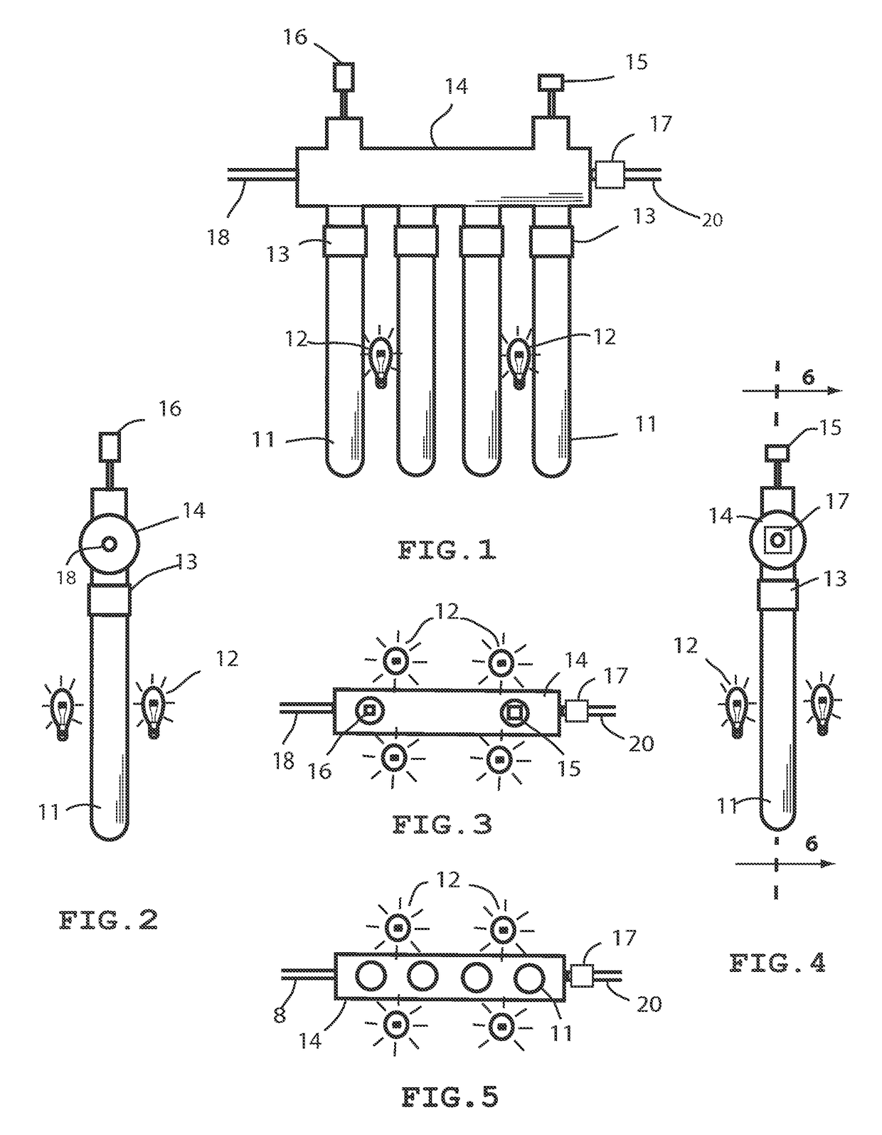
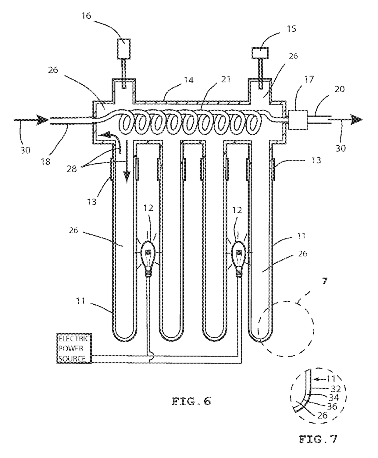
[0021]Referring now to the drawings and more particularly FIGS. 1-13. Shown are embodiments which comprise one or more evacuated tubes (11) and a header (14). Also illustrated in FIGS. 1-13 are one or more artificial light sources (12) in proximity to the evacuated tubes (11). FIG. 6 shows a cross section of the header (14) and evacuated tubes (11) forming an internal volume (26). FIG. 6 also shows a first heating fluid and its direction of flow represented by first heating fluid arrows (28) and hereafter referred to as the first heating fluid (28). FIG. 6 shows a second heating fluid and its direction of flow through the conduit system represented by second heating fluid arrows (30) and hereafter referred to as the second heating fluid (30). The internal volume (26) contains the first heating fluid (28) and the header conduit (21). The header conduit (21) conducts a second heating fluid (30) from influent conduit (18) through the header (14) and first heating fluid (28) to the effl...


PUM


Abstract

An evacuated tube boiler comprised of one or more evacuated tubes and a header, operatively connected to form a common internal volume. The internal volume further containing a first heating fluid. A conduit system conducting a second heating fluid through the header and first heating fluid. One or more artificial light sources in proximity to the evacuated tubes. In operation, the artificial light sources radiate light and / or thermal energy to the evacuated tubes whereby the first heating fluid is efficiently heated. The conduit system conducts the second heating fluid through the header and first heating fluid, whereby heat from the first heating fluid is transferred to the second heating fluid. The conduit system conducts the second heating fluid to the point of use. The apparatus may be used in a hydronic boiler heating system for heating a dwelling.

Description

CROSS REFERENCE TO RELATED APPLICATIONS[0001]This application claims priority to U.S. provisional application Ser. No. 61 / 850,333, filed Feb. 14, 2013, and incorporated herein by reference in its entirety.FIELD OF THE INVENTION[0002]The invention relates to boilers, or systems for heating water or other fluids.BACKGROUND OF THE INVENTION[0003]Most modern boilers typically used for hydronic heating are comprised of a gas fired or electric heating element, which heats water to a desired temperature, typically between about 100° F. to about 200° F., and then circulates the water through a conduit system to locations where heating is desired, wherein a means of heat exchange, typically a radiator, provides heat to the ambient air, thus warming the area or dwelling. With the cost of gas and electricity continuously increasing, this method of heating has become expensive to operate. There is a continuous desire to develop more efficient methods of converting energy in to heat, in particul...

Claims


Application Information

Patent Timeline
Patent Type & Authority Patents(United States)
IPC IPC(8): F24C1/00F24H1/00F24H1/16
CPCF24J2/055F24H1/0018F24J2/44F24D2220/07Y02E10/44F24H2250/14F24J2/345Y02B10/22F24H1/162F24S10/45F24S60/30F24S90/10Y02B10/20
Inventor DUNN, BRIAN
Owner DUNN BRIAN
Why Eureka
Try Eureka