Traction-battery vehicle test trailer

Active Publication Date: 2018-01-02
FORD GLOBAL TECH LLC
View PDF17 Cites 13 Cited by
  • Summary
  • Abstract
  • Description
  • Claims
  • Application Information

AI Technical Summary

Benefits of technology

The patent is for a trailer controller that can communicate with a vehicle's communication system to get information about the vehicle's speed and how quickly it's changing (accelerating or decelerating). This helps the controller to anticipate and respond to the vehicle's actions. The controller can then use this information to propel the frame of the trailer to match the vehicle's speed.

Problems solved by technology

Recharging of a traction-battery may require a specified voltage and rate of recharge, and during this time the vehicle may not be in test-ready condition.

Method used


Image

  • Traction-battery vehicle test trailer
  • Traction-battery vehicle test trailer

Examples


Embodiment Construction

[0015]The illustrated embodiments are disclosed with reference to the drawings. However, it is to be understood that the disclosed embodiments are intended to be merely examples that may be embodied in various and alternative forms. The figures are not necessarily to scale and some features may be exaggerated or minimized to show details of particular components. The specific structural and functional details disclosed are not to be interpreted as limiting, but as a representative basis for teaching one skilled in the art how to practice the disclosed concepts.

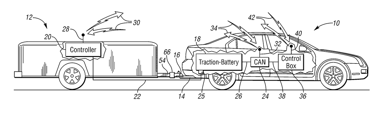
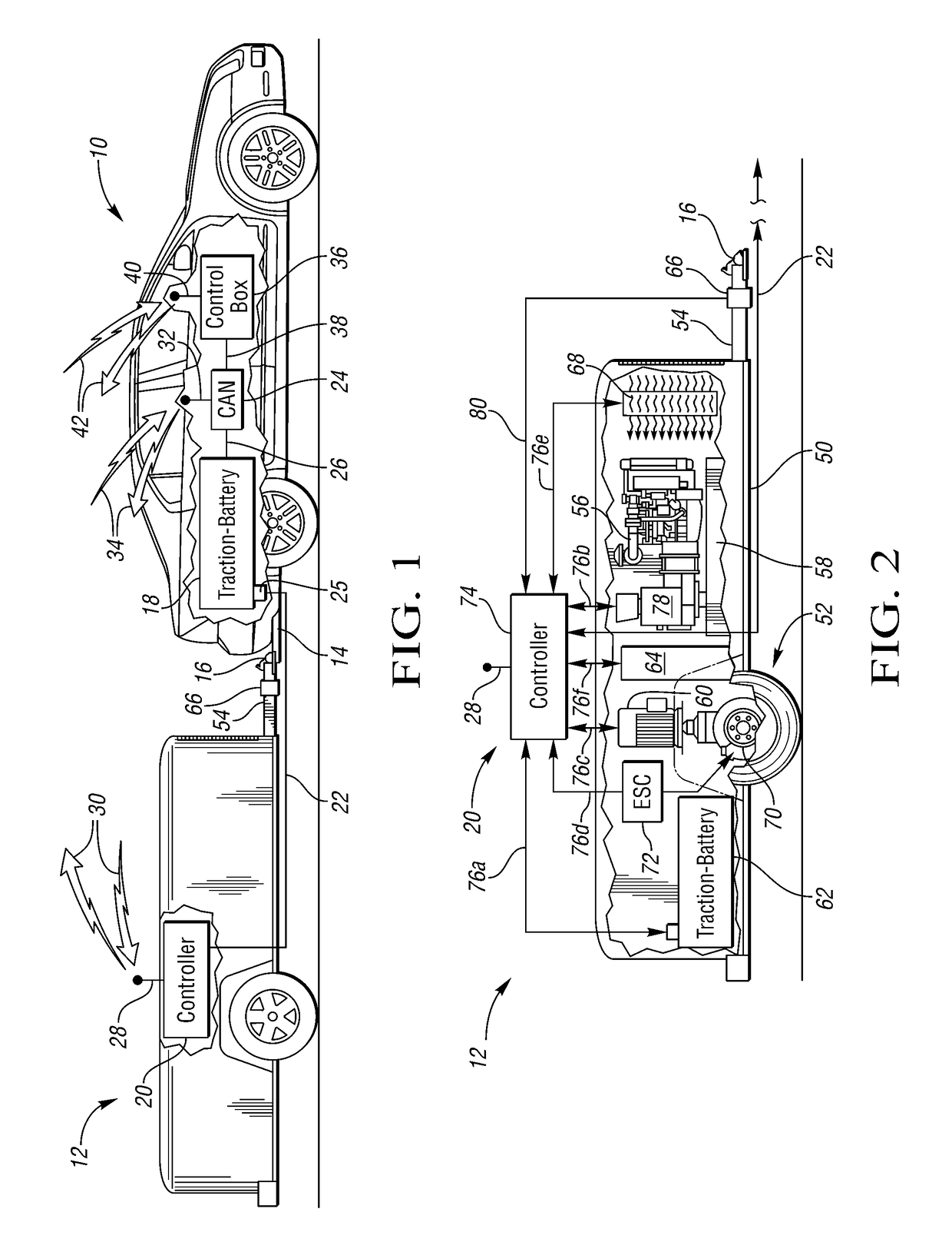
[0016]FIG. 1 shows a vehicle 10 connected to a trailer 12 via a hitch 14 and hitch coupler 16. Trailer 12 may also be referred to as test trailer 12 or recharging trailer 12. The vehicle 10 has a vehicle traction-battery 18 connected to a controller 20 on the trailer 12 via an electrical connection cable 22. The cable 22 has an electrical coupler 25 which allows the cable to connect to the traction-battery.

[0017]The electrical...


PUM


Abstract

A trailer for a vehicle with a high voltage traction-battery. The trailer may be a self-propelled trailer to substantially match vehicle dynamics and minimize impact on the vehicle. Alternatively, the trailer may push the vehicle to simulate hill descent, or drag on the vehicle to simulate hill ascent. The trailer may provide power for the vehicle. The trailer may provide current to a vehicle electric machine. The trailer may also provide current to recharge a vehicle traction-battery. The trailer may also recharge its own traction-battery.

Description

TECHNICAL FIELD[0001]This disclosure relates to testing trailers for vehicles having high voltage traction-batteries, and more specifically to self-propelled trailers that may substantially match vehicle dynamics to minimize impact on the vehicle during testing, push the vehicle to simulate hill descent, drag on the vehicle to simulate hill ascent, provide energy for the vehicle, and recharge the vehicle traction-battery as well as its own traction-battery, alone, or in any combination of the above.BACKGROUND[0002]Vehicular manufacturers often test vehicles to ensure that the vehicle's pass a certain level of durability and quality over the designed life of the vehicle. Since the designed life of modern vehicles may exceed decades of time and high mileages, the testing is often accelerated and compressed to provide useful results in a shorter period of time. These tests may vary in elapsed time, distance traveled, and may be run on unique surfaces or at special venues. One way to te...

Claims


Application Information

Patent Timeline
IPC IPC(8): B60K1/04B60L7/14B60W10/08B60K6/20G01L5/13B60L11/18B62D59/04B60L9/00
CPCG01L5/136B60L7/14B60L11/1803B60L11/1809B60L11/1816B60L11/1868B60L11/1877B60W10/08B62D59/04B60K6/20Y10S903/903B60K2001/0444B60L2200/28B60W2300/14B60W2530/22B60Y2200/147B60Y2200/91B60Y2300/28Y02T10/7005Y02T10/7066Y02T10/7072Y02T90/14B60W2530/207B60L50/51B60L50/66B60L53/14B60L58/20Y02T10/70
Inventor HAGAN, DANIEL LEE
Owner FORD GLOBAL TECH LLC
Why Eureka
Try Eureka