
GNSS long-code acquisition, ambiguity resolution, and signal validation

a long-code acquisition and signal validation technology, applied in the field of gnss, can solve the problems of difficult to operate high-power transmitters on orbit, difficult to operate positioning receivers in obstructed environments, and weak satellite-based navigation system signals, etc., to achieve rapid deployment, simple implementation, and cost-effective

Inactive Publication Date: 2018-01-02
TELECOMM SYST INC
View PDF2 Cites 7 Cited by
  • Summary
  • Abstract
  • Description
  • Claims
  • Application Information

AI Technical Summary

Benefits of technology

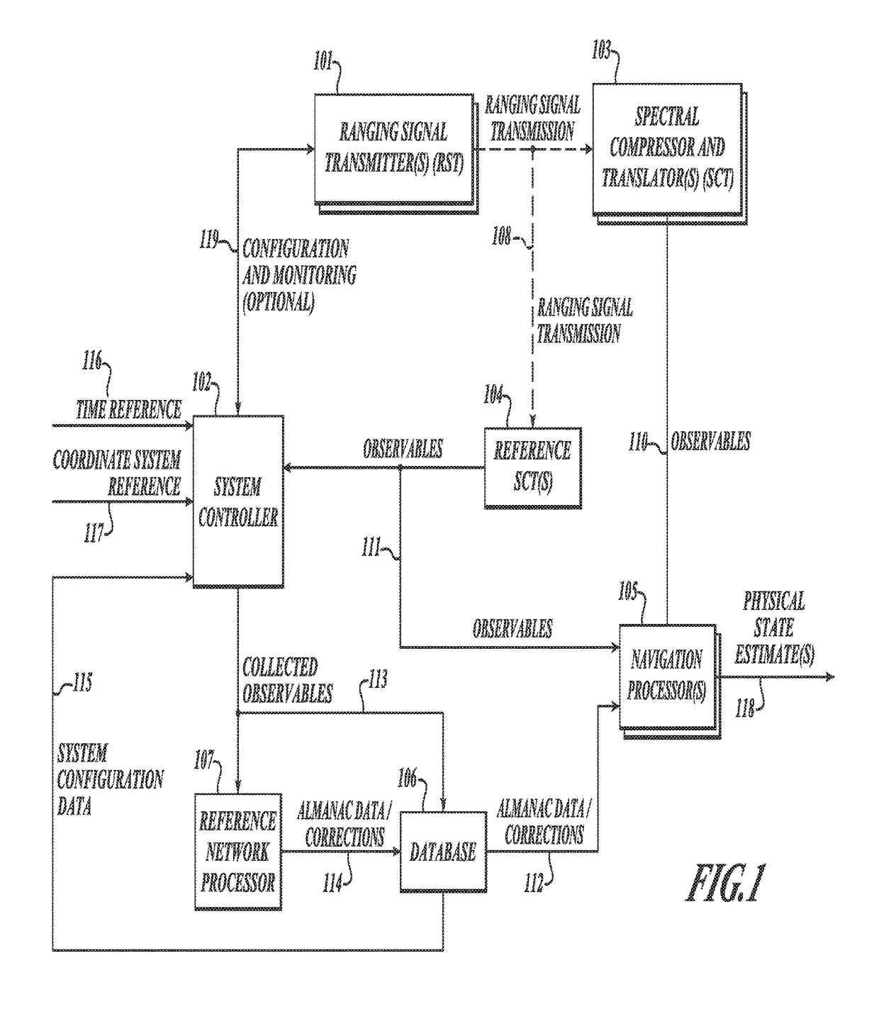
[0113]The preferred embodiment of the present invention facilitates a reduction in manufacturing cost and complexity of units implementing the SCT function while maximizing flexibility and performance. A further advantage of the present invention is achieved through integration of system functionality with wireless data communication functions, which allows sharing of digital signal processing and RF front-end circuits. As described in greater detail below, the SCT function of the present invention significantly reduces complexity and thus cost as compared to most wireless data communication receivers. By implementing SCT functions as an extension to the communications functions, physical state determination capabilities are added with little additional cost. Further, the integration with wireless data communications occurs naturally by combining sending / receiving data functions into the system controller.
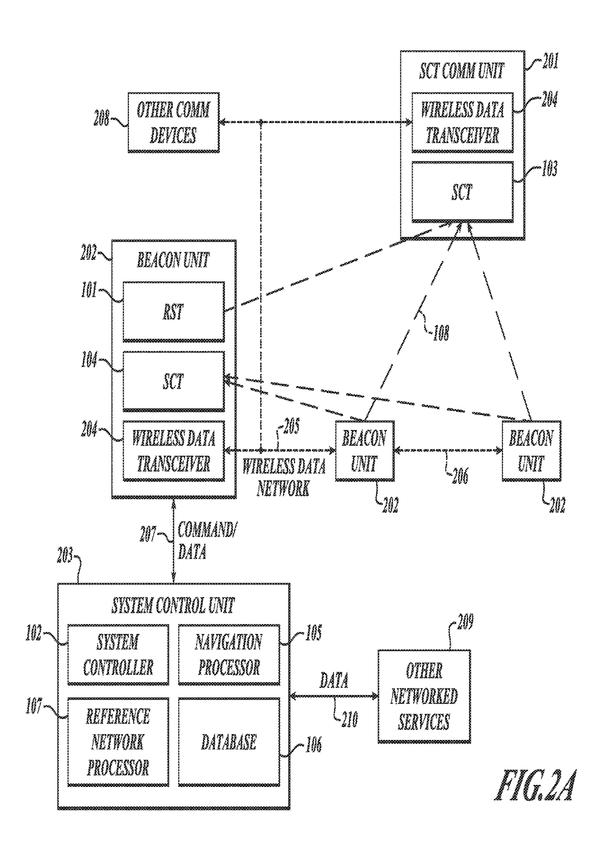
[0114]FIG. 2A shows the integration of the present invention with a meshed wireless data communications network such as Zigbee (802.15.4). An SCT 103 and wireless data transceiver 204 are combined to form an SCT communications unit 201. In its simplest form, the unit 201 represents a tag capable of RFID and physical state sensing. A beacon unit 202 is preferably comprised of an RST 101, SCT 104, and a wireless data transceiver 204. A plurality of beacon units is deployed over a physical area to provide both positioning ranging signals 108 and communications network infrastructure 205 and 206. The integration of an SCT 104 with the beacon unit enables each beacon unit to act as a reference SCT collecting observables from other beacon units deployed within range. Through this combined ranging transmission and collection of observables the system facilitates collection of the information necessary to determine its own configuration using the reference network processor 107. In one embodiment, the system controller 102, navigation processor 105, reference network processor 107 and database 106 are combined to form a system control unit 203 that centralizes the complex data processing and management functions. The system control unit 203 is preferably connected to the wireless data network 205 via one or more beacon units through a communication signal 207. For wireless data networks supporting meshed networking, beacon units 202 become nodes in wireless data networks 205 and 206. Meshed network deployment effectively simplifies installation of the location system enabling each beacon unit 202 to coordinate with the system control unit 203 via other beacons units without requiring installation of other communication mediums (e.g. Ethernet). In the preferred embodiment of the present invention, the system control unit is physically connected to one or more beacon units via an Ethernet connection, which provides advantages of robustness and reduced cost. For greater portability and flexibility, the communication signal 207 may be accomplished by connecting a wireless data transceiver 204 directly to the system control unit 203.
[0115]Once deployed, as integrated with a wireless data communications network (shown in FIG. 2A), the present invention can also be used for a variety of data networking applications between communication devices 208 and networked services 209 external to the system. As discussed in further detail below, the communication requirements for the present invention minimize the need for communications resources, leaving the bulk of the bandwidth available for other activities. In the preferred embodiment, the system control unit 203 is a gateway for networked services to access devices on the wireless data networks 205 and 206. The wireless data networks 205 and 206 may be secured by data encryption and other security means such that only authorized user is able to access and use the beacon unit 202 and system control unit 203 gateway infrastructure for relaying information between devices and services.
[0116]FIG. 2B shows an alternate embodiment of the SCT communications unit 201 where the navigation processor 105 is integrated directly with the SCT 103 and wireless data transceiver 204 functions. This configuration enables calculation of SCT state vector 118 at the unit in situations where almanac and data corrections 112 are available from the system. The almanac and data corrections 112 are delivered to the SCT communications unit 201 a priori or on demand as requested by the unit 201. In an alternative embodiment, the unit 201 may request observables from one or more reference SCTs to determine a full differential solution. Similar to the configuration of FIG. 2A, the semi-autonomous configuration described in FIG. 2B may utilize system control unit determined physical state estimates as needed. For example, this capability may be useful in situations where the navigation processor 105 is unavailable due to limited power resources.
[0117]FIG. 2C shows an alternate embodiment of the SCT communications unit 201 in which a machine to machine interface (MMI) 235 is integrated with core SCT functions 103 and wireless data transceiver functions 204 to provide SCT physical state estimate (PSE) 118 and data communications 233 for external devices 234. This configuration is typical of a location-enabled communications peripheral, where the external device 234 includes custom driver software enabling it to access physical state determination and communications functions of the SCT communications unit 201. This configuration represents a low-cost implementation with respect to SCT communications unit complexity. In this embodiment, the observables 111 are processed by the system control unit 203, which returns the resultant physical state estimate 118. This information is relayed by the SCT communications unit 201 to the external device 234 via the MMI 235.
[0118]FIG. 2D shows an alternative embodiment of the SCT communications unit 201 where both a navigation processor 105 and an MMI 235 are integrated with the core SCT functions 103 and wireless data transceiver functions 204 to provide a semi-autonomous positioning capability. Similar to the embodiment shown in FIG. 2B, this embodiment is capable of determining the SCT physical state estimate (PSE) 118 in situations where the systems control unit 203 delivers appropriate almanac data and corrections 112. As with FIG. 2C, the SCT communications unit 201 provides PSE 118 and data communications 233 to an external device 234.

Problems solved by technology

Despite its many advantages, GNSS has one significant drawback: satellite-based navigation systems signals are typically very weak as they reach the positioning receiver.
In some cases, like the GPS, this is a key part of its design, but practically it is difficult to operate high power transmitters on orbit.
These weak signals make it difficult to operate positioning receivers in obstructed environments, such as indoors, as the obstructions will tend to attenuate the signal power and render it useless for positioning or, at the very least, substantially degrade the overall measurement capability.
While significant effort has been made to overcome these limitations, particularly Assisted GPS and High-Sensitivity GPS, in practical terms meter level positioning in obstructed environments using GNSS is not feasible for broad usage.
While promising, RTLS systems are very expensive to install and operate.
When high accuracy is needed, the cost and complexity of the equipment can make it all but impractical except for a few limited applications.
RTLS offers a variety of solutions that can be tailored to fit a variety of applications; however, when compared to the relative simplicity and wide availability of GNSS based positioning they all are less than desirable.
Further, for combined applications requiring positioning in both local area obstructed and wide area unobstructed environments, options are extremely limited as neither GNSS nor RTLS can satisfy the requirement alone.
Combined RTLS and GNSS systems are impractical due to the fact that they are largely incompatible and are difficult to integrate and, as a result, very expensive.
While attractive in concept, these solutions are at best too expensive and power intensive to be practical in addressing many of the RTLS applications and at worst they are illegal to operate in much of the world as they tend to jam normal GPS operations.

Method used


Image

  • GNSS long-code acquisition, ambiguity resolution, and signal validation
  • GNSS long-code acquisition, ambiguity resolution, and signal validation
  • GNSS long-code acquisition, ambiguity resolution, and signal validation

Examples


Embodiment Construction

[0079]There are situations in which a GNSS implementation for determining the physical state of some sensor is impractical because the satellites signals are either too weak, obstructed or interfered with by accident or intent. Such situations can occur in an enclosed space such as within a metal constructed warehouse, below ground / rubble, or possibly GNSS jamming environments.

[0080]By way of overview, the present invention utilizes a beacon constellation environment, which although low in transmitter power (<1 microwatt), provides signal flux that is 40 to 60 dB more powerful than GNSS signals and thus is able to determine the physical state of a sensor in missions where GNSS is either absent or unreliable in the context of a configured environment or, in other words, an environment in which there is the ability to deploy a beacon constellation in a manner that affords the maximum of flexibility for the system operator. The constellation of beacons uses spread spectrum techniques w...


PUM


Abstract

The present invention relates to a system and method using hybrid spectral compression and cross correlation signal processing of signals of opportunity, which may include Global Navigation Satellite System (GNSS) as well as other wideband energy emissions in GNSS obstructed environments. Combining spectral compression with spread spectrum cross correlation provides unique advantages for positioning and navigation applications including carrier phase observable ambiguity resolution and direct, long-code spread spectrum signal acquisition. Alternatively, the present invention also provides unique advantages for establishing the validity of navigation signals in order to counter the possibilities of electronic attack using spoofing and / or denial methods.

Description

[0001]This application is a continuation of U.S. patent application Ser. No. 13 / 897,278, filed 17 May 2013, now U.S. Pat. No. 9,358,341, which is a continuation-in-part of U.S. patent application Ser. No. 13 / 029,966, filed 17 Feb. 2011, now abandoned, which is a continuation of U.S. patent application Ser. No. 12 / 372,235, filed 17 Feb. 2009, now U.S. Pat. No. 7,916,074, which is a continuation of U.S. patent application Ser. No. 11 / 697,575, filed 6 Apr. 2007, now U.S. Pat. No. 7,511,662, which claims priority to U.S. Provisional Application No. 60 / 745,928, filed 28 Apr. 2006 and to U.S. patent application Ser. No. 13 / 269,426, filed 7 Oct. 2011, now U.S. Pat. No. 9,239,376, and further claims priority to U.S. Provisional Application No. 61 / 648,533, filed 17 May 2012, which applications are hereby incorporated by reference in their entirety as if fully set forth herein.FIELD OF THE INVENTION[0002]The invention generally relates to a system and method for positioning and navigation of ...

Claims


Application Information

Patent Timeline
Patent Type & Authority Patents(United States)
IPC IPC(8): G01S19/14G01S19/37G01S19/23G01S19/21G01S19/24G01S5/02G01S11/10G01S19/11
CPCG01S19/215G01S5/021G01S5/0289G01S11/10G01S19/11G01S19/14G01S19/23G01S19/246G01S19/37G01S19/46G01S19/48G01S1/024G01S1/08G01S1/24
Inventor MATHEWS, MICHAEL B.MACDORAN, PETER F.
Owner TELECOMM SYST INC
Learn More