Master cylinder for brake system

a brake system and master cylinder technology, applied in the direction of fluid braking transmission, etc., can solve the problem of not being able to effectively control the flow of brake liquid, and achieve the effect of reducing lost travel, effective prevention of braking pressure, and improving braking reaction

Active Publication Date: 2018-01-09
HL MANDO CORP
View PDF3 Cites 2 Cited by
  • Summary
  • Abstract
  • Description
  • Claims
  • Application Information

AI Technical Summary

Benefits of technology

[0012]A master cylinder for a brake system, according to an embodiment of the present invention, reduces the lost travel in order to allow a prompt braking operation.
[0013]Also, a master cylinder for a brake system, according to an embodiment of the present invention, prevents a braking pressure from being generated irrespective of the intention of the driver.
[0024]The fluid resistance hole may include a porous filter to reduce the fluid velocity of the brake liquid that is discharged through the brake liquid discharge opening during a braking operation.
[0025]According to a master cylinder for a brake system, according to an embodiment of the present invention, a lost travel can be reduced and a braking reaction can be improved by promptly increasing the initial amount of liquid during a braking operation of a first liquid pressure chamber and a second liquid pressure chamber by installing a value unit including a fluid resistance hole in a brake liquid port.
[0026]Furthermore, according to a master cylinder for a brake system according to an embodiment of the present invention, braking pressure can be effectively prevented from being generated irrespective of the intention of the driver by installing a valve unit including a fluid resistance hole in a brake liquid port and thus preventing the brake liquid of the liquid pressure chamber from being abnormally expanded.

Problems solved by technology

Because the brake liquid port 9 simply functions as a passage for the brake liquid between the master cylinder and the reservoir, it cannot effectively control the flow of the brake liquid according to the pressure of the liquid pressure chambers that are necessary when a prompt braking operation is required.

Method used


Image

  • Master cylinder for brake system
  • Master cylinder for brake system
  • Master cylinder for brake system

Examples


Embodiment Construction

[0033]Hereinafter, exemplary embodiments of the present invention will be described with reference to the accompanying drawings. Before the description, the terms or words used in the specifications and claims should not be limited to be construed as usual or dictionary definition but should be rather construed to be consistent with the technical spirits of the present invention based on the principle that the inventors may properly define the terms used in the specification to describe their invention in the best manner. Accordingly, it should be understood that the embodiments described in the specification and configurations disclosed in the drawings are merely examples and do not represent all of the technical spirits of the invention and various modifications and variations to the invention and equivalents thereof may be made at the time of the invention

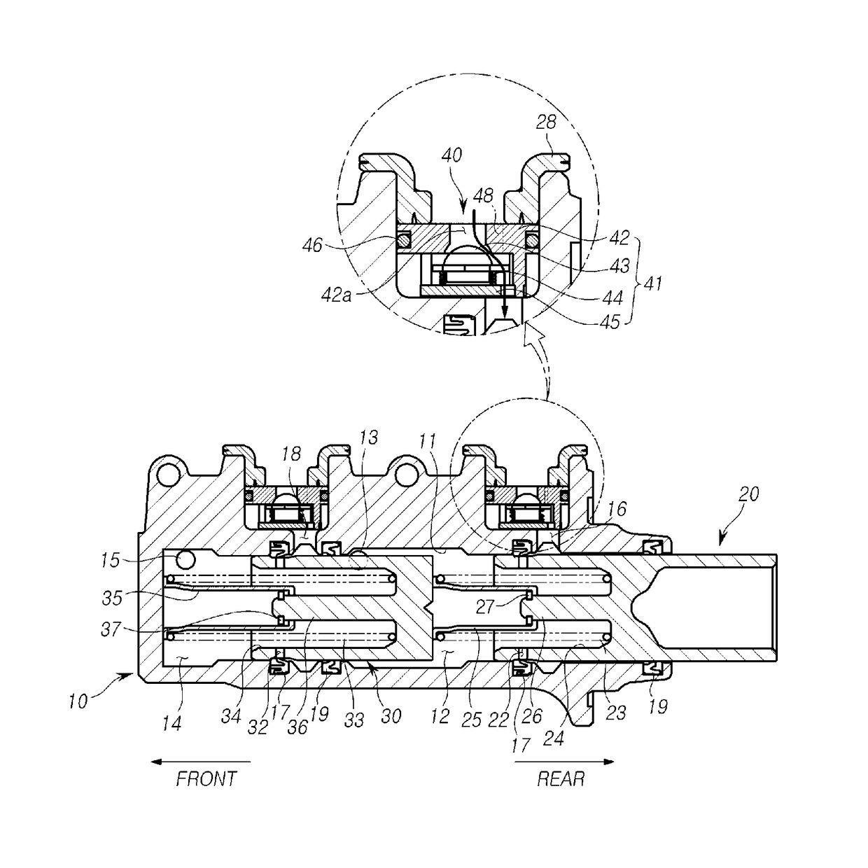
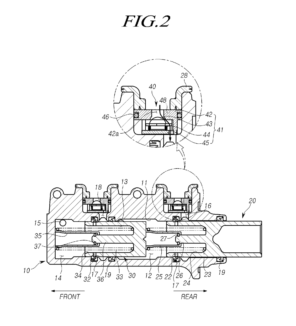
[0034]FIG. 2 is a view illustrating a master cylinder for a brake system according to an embodiment of the present invention.

[...


PUM


Abstract

Disclosed is a master cylinder for a brake system. The master cylinder includes a cylinder body that has a bore therein; at least one piston provided in the bore to be moved forwards and rearwards; a liquid pressure chamber compressed by the piston; a brake liquid port that is connected to a reservoir and configured to supply brake liquid to the liquid pressure chamber; and a brake liquid discharge opening for discharging the brake liquid in the liquid pressure chamber to a wheel brake of a wheel. A valve unit that includes a check valve to control the unidirectional flow of the brake liquid that is introduced from the reservoir to the liquid chamber and a fluid resistance hole opened in two directions and is smaller than the size of the brake liquid discharge opening is provided in the brake liquid port.

Description

CROSS-REFERENCE TO RELATED APPLICATION[0001]This application claims priority from and the benefit under 35 U.S.C. §119(a) of Korean Patent Application No. 10-2014-0143899, filed on Oct. 23, 2014, which is hereby incorporated by reference for all purposes as if fully set forth herein.BACKGROUND OF THE INVENTION[0002]1. Field of the Invention[0003]The present invention relates to a master cylinder for a brake system, and more particularly, to a a master cylinder for a brake system that can improve a braking feeling.[0004]2. Description of the Prior Art[0005]In a vehicle's hydraulic brake system, a master cylinder is an apparatus that generates hydraulic pressure according to the pedaling of the driver and sends the hydraulic pressure that is necessary to the brakes that are installed in the wheels of the vehicle in order to perform the braking operation.[0006]FIG. 1 illustrates a general tandem type master cylinder. Referring to the drawing, the master cylinder includes a first piston...

Claims


Application Information

Patent Timeline
Patent Type & Authority Patents(United States)
IPC IPC(8): B60T11/28B60T11/22B60T11/16
CPCB60T11/28B60T11/22B60T11/16
Inventor KANG, DONG KOO
Owner HL MANDO CORP
Why Eureka
Try Eureka