
Electric power measuring system

a technology of electric power measuring system and measurement accuracy, which is applied in the direction of instruments, electric devices, base element modifications, etc., can solve the problems of affecting the reliability of the typical electric power measuring system b>1/b>, and affecting the accuracy of the typical electric power measuring system. achieve the effect of improving the measurement reliability of the electric power measuring system and reducing the computation amount of the integrated measuring instrumen

Active Publication Date: 2018-01-09
LSIS CO LTD
View PDF17 Cites 0 Cited by
  • Summary
  • Abstract
  • Description
  • Claims
  • Application Information

AI Technical Summary

Benefits of technology

The present patent aims to provide an electric power measuring system that can accurately measure the electric power of a distribution line using a current measuring instrument installed inside a distribution panel or a panel board. The system ensures that the phases of the voltage and current measured at the distribution line are synchronized, resulting in improved measurement reliability. Additionally, the system reduces the computation required by transmitting the relative phase between the current and voltage of the distribution line through the current measuring instrument.

Problems solved by technology

Meanwhile, in a small-scale distribution panel or panel board, an electric power measuring system is established with only a low voltage measuring instrument due to a manufacture cost factor.
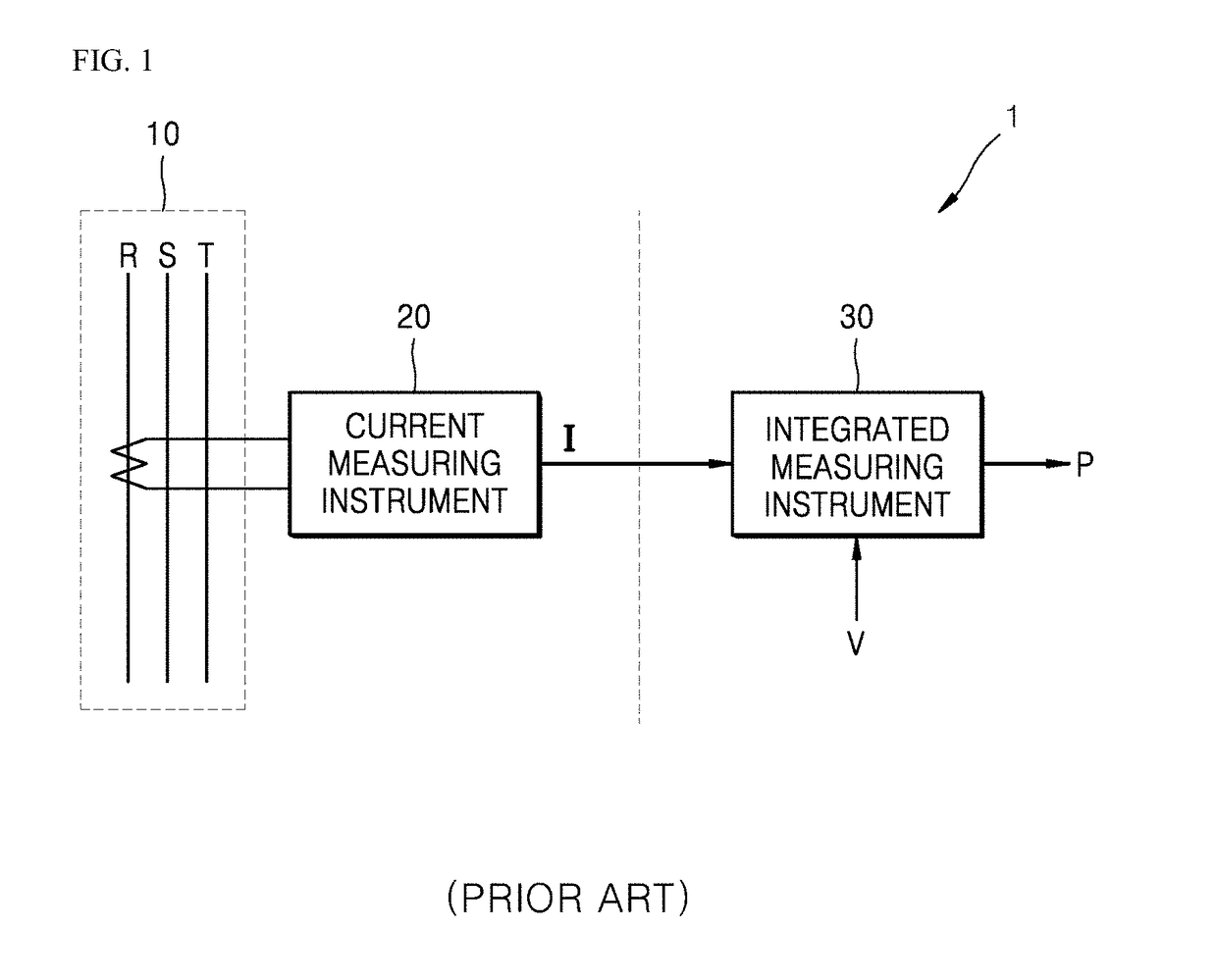
In the typical electric power measuring system 1, however, when the current measuring instrument 20 transmits the current information I to the integrated measuring instrument 30, a problem in which a phase of the current information I is not synchronized with that of the voltage information V may occur due to a time delay and the like.
Consequently, it is difficult to accurately compute the electric power information P of the distribution line 10 to cause a problem in which reliability of the typical electric power measuring system 1 is degraded.

Method used


Image

  • Electric power measuring system
  • Electric power measuring system
  • Electric power measuring system

Examples


Embodiment Construction

[0029]Hereinafter, an electric power measuring system according to some embodiments of the present disclosure will be described in detail with reference to the accompanying drawings.

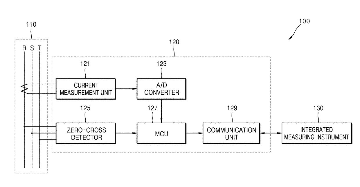
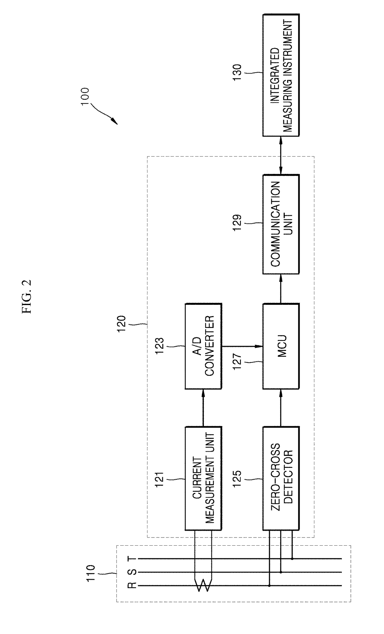
[0030]FIG. 2 is a diagram schematically illustrating a configuration of an electric power measuring system according to an embodiment of the present disclosure.

[0031]With reference to FIG. 2, an electric power measuring system 100 may include a current measuring instrument 120 and an integrated measuring instrument 130 which are connected to each other through wire / wireless communication networks (not shown) to perform a data communication.

[0032]One or more current measuring instruments 120 may be installed inside a panel board or a distribution panel. The current measuring instrument 120 may generate current information according to a current measured from a distribution line 110 inside the panel board or the distribution panel to transmit the current information to the integrated measuring instrument 1...


PUM


Abstract

Embodiments of an electric power measuring system capable of computing accurate electric power information using a low voltage measuring instrument in a small-scale electric power system are provided. The electric power measuring system may include a first measuring instrument for measuring and detecting a current and a zero-cross point from a distribution line and for generating and outputting current information of the distribution line from the current and the zero-cross point, and a second measuring instrument for computing electric power information of the distribution line according to a voltage thereof and the current information output from the first measuring instrument.

Description

CROSS REFERENCE TO RELATED APPLICATIONS[0001]This application claims the benefit of Korean Patent Application No. 10-2015-0099936, filed on Jul. 14, 2015 entitled “ELECTRIC POWER MEASURING SYSTEM”, which is hereby incorporated by reference in its entirety.BACKGROUND[0002]Technical Field[0003]The present disclosure relates to an electric power measuring system, and more particularly, to an electric power measuring system capable of computing accurate electric power information using a low voltage measuring instrument in a small-scale electric power system.[0004]Description of the Related Art[0005]Generally, an electric power measuring system measures a voltage and a current flowing at an electric power system in a distribution panel or a panel board, that is, a load of a distribution line to compute electric power information such as electric energy and the like through various computations.[0006]The electric power measuring system includes a measuring instrument for measuring a volt...

Claims


Application Information

Patent Timeline
Patent Type & Authority Patents(United States)
IPC IPC(8): G01R1/20G01R19/175G01R21/133G01R15/18G01R21/00
CPCG01R21/133G01R19/175G01R21/005G01R21/002
Inventor AHN, HONG-SEON
Owner LSIS CO LTD
Learn More