
Optical liquid level detection sensor and liquid overfill prevention system comprising such sensor

a technology of optical liquid level detection and detection sensor, which is applied in the direction of machines/engines, instruments, and containers discharging methods, etc., can solve the problems of liquid entering the interior of the sensor, the connection between the metal retention ring and the prism, and the relative difficulty of assembly between the metal retention ring and the probe body

Active Publication Date: 2018-01-16
OPW FLUID TRANSFER GROUP EURO
View PDF9 Cites 0 Cited by
  • Summary
  • Abstract
  • Description
  • Claims
  • Application Information

AI Technical Summary

Benefits of technology

[0016]By providing a sensor comprising an at least partially transparent ring element, wherein the liquid contact surface is formed by an outer surface of the ring element, the ring element of the sensor can be easily and reliably placed in a sealing engagement with other parts of the sensor. In particular, the ring element may have planar sealing surfaces at opposed sides of the ring element. These sealing surfaces are very suitable to create a sealing engagement between the ring element and other parts of the sensor.
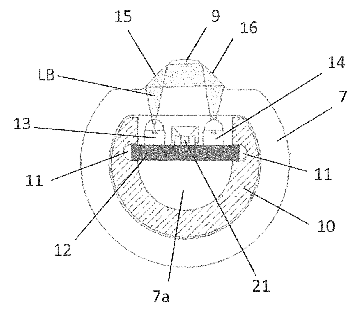
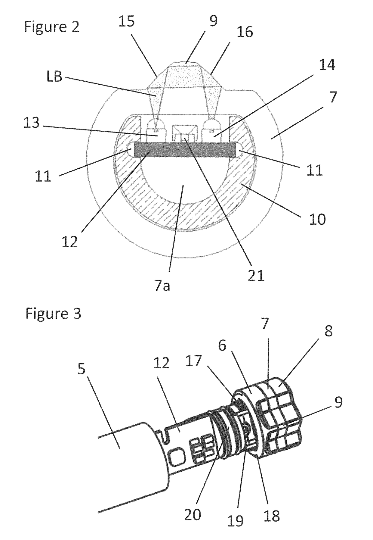
[0018]In an embodiment, the light source and / or light detector are arranged in the inner space of the ring element. The ring element defines an inner space. By arranging the light source and / or light detector in this inner space a compact construction is obtained. The ring element may comprise one or more inner spaces running through the ring element. The one or more inner spaces may be used to make a connection possible between two parts at opposite sides of the ring element to pull the two parts towards each other to create a sealing engagement between the ring element and each of the two parts.
[0035]Such additional ground system has the advantage that when the ground cable of the standard ground connection no longer provides a ground connection, for example when the cable is disconnected from an associated connector, the sensor is still connected to earth via the additional ground connection.
[0038]In an embodiment, the sensor comprises two or more ring elements spaced with respect to each other, wherein the two or more ring elements each form a liquid contact surface associated with a light source and a light detector. The use of ring elements to form liquid contact surfaces has the further advantage that the liquid contact surface is arranged at the side of the sensor, while a printed circuit board can pass through the inner of the ring element. This makes it possible to arrange in a single sensor multiple ring elements spaced with respect to each other, wherein the two or more ring elements each form a liquid contact surface associated with a light source and a light detector.
[0044]The liquid level detection sensors may be arranged in an upper part of the interior of a compartment of a truck, for example to detect whether the compartment is filled to a predetermined level. The liquid level detection sensors may also be arranged in a lower part of the interior of the compartment, for example to detect whether the compartment is sufficiently empty, e.g. not filled at a level above the location of the level detection sensor so that a desired quantity of liquid can be introduced into the compartment without overfilling the compartment.

Problems solved by technology

A drawback of such construction is that the press-fitted connection between the metal retention ring and the prism and between the metal retention ring and the probe body is relatively difficult to assemble.
As a result, there is a risk that the sensor is not properly sealed, and that liquid can enter the interior of the sensor.
A further drawback of this construction is that the press-fitted connection cannot be taken apart without damage to the prism, metal retention ring and / or probe body.

Method used


Image

  • Optical liquid level detection sensor and liquid overfill prevention system comprising such sensor
  • Optical liquid level detection sensor and liquid overfill prevention system comprising such sensor
  • Optical liquid level detection sensor and liquid overfill prevention system comprising such sensor

Examples


Embodiment Construction

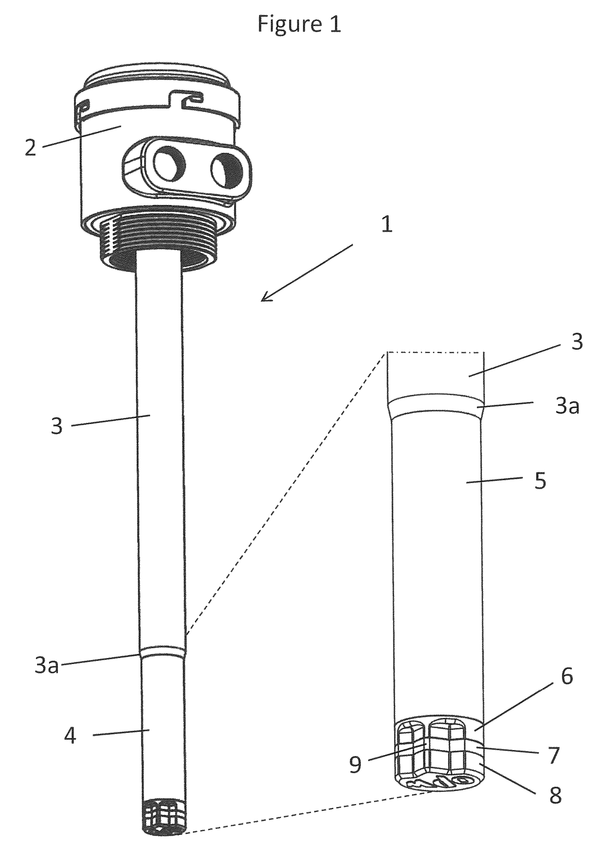
[0053]FIG. 1 shows a perspective view of an optical liquid level detection sensor unit according to the invention, generally indicated by reference numeral 1. The sensor unit 1 comprises a sensor mounting device 2, a sensor support tube 3 and a sensor device 4. The sensor device 4 is shown enlarged at the right side of FIG. 1.

[0054]The sensor mounting device 2 may be of a standard type to mount the sensor unit 1 in an opening at the top side of a compartment of a truck. The sensor device 4 is connected to the sensor support tube 3, for example by a screw connection. The sensor device 4 may be connected to other devices, such as a monitoring system, by a number of sensor cables running through the sensor support tube 3.

[0055]The sensor unit 1 is configured as a part of a liquid overfill prevention system configured to avoid that a compartment is overfilled with liquid, in particular dangerous goods, such as flammable liquids, in particular liquid fuels.

[0056]Typical requirements for ...


PUM

PropertyMeasurementUnit
transparentaaaaaaaaaa
timeaaaaaaaaaa
flammableaaaaaaaaaa

Abstract

An optical liquid level detection sensor includes a light source for emitting a light beam, a liquid contact surface, and a light detector, where the light source is arranged to emit a light beam towards the liquid contact surface, which liquid contact surface reflects or transmits the light beam in dependence of liquid being present on the liquid contact surface, where the light detector is arranged to receive the light beam after reflection on the liquid contact surface, where the sensor includes an at least partially transparent ring element, and where the liquid contact surface is formed by an outer surface of the ring element.

Description

CROSS-REFERENCE TO RELATED APPLICATIONS[0001]This application is the National Stage of International Application No. PCT / NL2014 / 050049 filed Jan. 30, 2014, which claims the benefit of Netherlands Application No. 2010203, filed Jan. 30, 2013, the contents of which is incorporated by reference herein.FIELD OF THE INVENTION[0002]The present invention relates to an optical liquid level detection sensor, in particular for flammable liquids such as liquid fuels, and to a liquid overfill prevention system comprising such sensor. Optical liquid level detection sensors are configured to determine, using a light beam, whether liquid is present on a liquid contact surface of the sensor. Such sensors are known to be used in a liquid overfill prevention system. A liquid overfill prevention system is configured to monitor whether a compartment of a truck or another liquid container will not be overfilled.BACKGROUND OF THE INVENTION[0003]WO 2008 / 076720 discloses an optical level detection sensor f...

Claims


Application Information

Patent Timeline
Patent Type & Authority Patents(United States)
IPC IPC(8): G01N15/06G01F23/292F17C13/02
CPCG01F23/292G01F23/2927G01F23/2925F17C13/021
Inventor KORS, LEONARDUS ALEXIUSVAN DER MAARL, ARIE PIETER WILHELMUSDE BOER, JAN CORNELIS
Owner OPW FLUID TRANSFER GROUP EURO
Learn More