Wireless power receiver and power control method thereof

a power receiver and wireless technology, applied in the direction of electrochemical generators, secondary cell servicing/maintenance, transportation and packaging, etc., can solve the problems of unstable battery charge state and short power transmission distan

Active Publication Date: 2018-01-16
LG INNOTEK CO LTD
View PDF20 Cites 5 Cited by
  • Summary
  • Abstract
  • Description
  • Claims
  • Application Information

AI Technical Summary

Benefits of technology

[0008]The embodiment provides a method of preventing a wireless power transmission system from being erroneously operated through a power control algorithm when power is wirelessly transmitted using electromagnetic induction or resonance.
[0009]The embodiment provides a method capable of greatly improving the power transmission efficiency of a wireless power transmission system through a power control algorithm when power is wirelessly transmitted using electromagnetic induction or resonance.
[0010]The embodiment provides a method capable of stably supplying power by improving a charged state of a battery through a power control algorithm when power is wirelessly transmitted using electromagnetic induction or resonance.
[0025]The wireless power transmission system may be prevented from being out of order and may be stably operated through a power control algorithm when power is wirelessly transmitted by using electromagnetic induction or resonance.
[0026]The power transmission efficiency of the wireless power transmission system may be greatly improved through the power control algorithm.
[0027]In addition, the charged state of a battery is improved through the power control algorithm, so that it is possible to stably supply power.

Problems solved by technology

Although the commercialization of the electromagnetic induction technology has been rapidly progressed around small-size devices, the power transmission distance is short.
However, in the related art, as the voltage applied to a battery is changed, the charged state of the battery is unstable.

Method used


Image

  • Wireless power receiver and power control method thereof
  • Wireless power receiver and power control method thereof
  • Wireless power receiver and power control method thereof

Examples


second embodiment

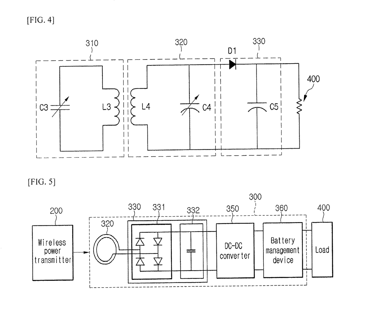
[0080]FIG. 5 is a block diagram showing a wireless power receiver 300 according to a

[0081]Referring to FIG. 5, the wireless power receiver 300 may include the reception induction coil 320, the rectifying unit 330, the DC-DC converter 350, and a battery management IC (BMIC) 360. According to the embodiment, if the wireless power receiver 300 receives power from the wireless power transmitter 200 through the resonance, the wireless power receiver 300 may further include the reception resonant coil 310. According to the embodiment, if the wireless power receiver 300 receives power from the wireless power transmitter 200 through the electromagnetic induction, the wireless power receiver 300 may not include the reception resonant coil 310.

[0082]The reception induction coil 320 receives power from the wireless power transmitter 200. The power received in the reception induction coil 320 may be AC power.

[0083]The rectifying unit 330 may convert the AC power received in the reception induct...

first embodiment

[0099]FIG. 6 is a flowchart illustrating a power control method of a wireless power receiver 300 according to a

[0100]Details of the wireless power receiver 300 are equal to those shown in FIG. 5.

[0101]It is assumed in the following description that the load 400 is a battery embedded in an electronic appliance such as a portable phone or a laptop computer.

[0102]Referring to FIG. 6, first, in step S101, the BMIC 360 determines whether the load 400 operates in a non-charging mode. The non-charging mode may signify that power is not supplied to the load 400. To the contrary, a charging mode may signify that power having a predetermined level or more is continuously supplied to the load 400.

[0103]In step S103, if the BMIC 360 confirms that the load 400 is in the non-changing mode, the BMIC 400, the BMIC 360 applies a voltage equal to or higher than a threshold voltage to the load 400. According to an embodiment, the threshold voltage may refer to the minimum voltage required to allow the...

third embodiment

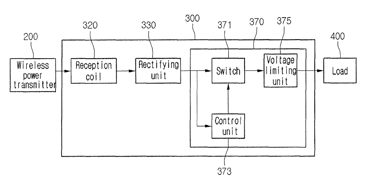
[0113]FIG. 7 is a block diagram showing a wireless power receiver 300 according to a

[0114]Referring to FIG. 7, the wireless power receiver 300 may include a reception induction coil 320, a rectifying unit 330 and a charging management unit 370.

[0115]In addition, although not shown in FIG. 7, the wireless power receiver 300 may further include a DC-DC converter 350 shown in FIG. 5.

[0116]In addition, although not shown in FIG. 7, the wireless power receiver 300 may further include a battery management device (BMIC) 360 shown in FIG. 5.

[0117]The BMIC 360 may control the DC power in order to charge the load 400 with a constant DC current.

[0118]The BMIC 360 may be included in the load 400. Hereinafter, it is assumed in the description that the BMIC 360 is included in the load 400.

[0119]According to the embodiment, if the wireless power receiver 300 receives power from the wireless power transmitter 200 through the resonance, the wireless power receiver 300 may further include a reception...


PUM

PropertyMeasurementUnit
threshold voltageaaaaaaaaaa
timeaaaaaaaaaa
poweraaaaaaaaaa

Abstract

A method of controlling power in a wireless power receiver to wirelessly receive power from a wireless power transmitter and transmit the power to a load, the method comprising of receiving AC power from the wireless power transmitter that receives power from a power supply device, rectifying the AC power to DC power and controlling DC power applied to the load by comparing the DC power with a threshold voltage.

Description

CROSS-REFERENCE TO RELATED APPLICATIONS[0001]This application is a Continuation of U.S. patent application Ser. No. 14 / 397,102 filed on Oct. 24, 2014, which is the National Phase of PCT International Application No. PCT / KR2013 / 003654 filed on Apr. 26, 2013, which claims the benefit of priority of Korean Patent Application No. 10-2012-0044148 filed on Apr. 26, 2012, all of which are hereby expressly incorporated by reference into the present application.BACKGROUND OF THE INVENTION[0002]The embodiment relates to a wireless power receiver and a power control method thereof. A wireless power transmission or a wireless energy transfer refers to a technology of wirelessly transferring electric energy to desired devices. In the 1800's, an electric motor or a transformer employing the principle of electromagnetic induction has been extensively used and then a method for transmitting electrical energy by irradiating electromagnetic waves, such as radio waves or lasers, has been suggested. Ac...

Claims


Application Information

Patent Timeline
Patent Type & Authority Patents(United States)
IPC IPC(8): H01M10/44H01M10/46H02J7/02H02J50/12H02J7/00H02J50/90
CPCH02J7/008H02J50/90H02J50/12H02J7/025H02J5/005H02J50/10H02M7/2176H02J7/00712H02J50/40H02J7/007184H02J7/0047H04B5/0037
Inventor BAE, SU HO
Owner LG INNOTEK CO LTD
Why Eureka
Try Eureka