Partial detect mode

a touch system and function technology, applied in the direction of power supply for data processing, instruments, computing, etc., can solve the problems of limited power access and mechanical parts are therefore sensitive to mechanical failure, and achieve the effect of low power function

Inactive Publication Date: 2018-01-23
FLATFROG LAB
View PDF646 Cites 31 Cited by
  • Summary
  • Abstract
  • Description
  • Claims
  • Application Information

AI Technical Summary

Benefits of technology

[0013]As only a subset of the distributed control devices, e.g. one or two, are used in the partial detect mode, power consumption can be kept very low. As less power is used, one control device can be used for both emitting and detecting at the same time as fewer disturbances will be introduced into the control device during detection. In a normal operation, a distributed control device is used for only emitting or detection at the same time to not compromise any detection results, as currents necessary for emitting light otherwise might disturb the detection result.
[0016]According to one embodiment, the distributed control devices are grouped into at least one group. All the distributed control devices may be grouped into the same group, and then there is only one group. Instead, the distributed control devices may be divided into two or more groups. According to one embodiment, the distributed control devices in each group are connected in series. By having the distributed control devices connected in series, the need for separate cables between each distributed control device and the main control unit is obviated. Thus, space can be saved and less cable length is needed. Disturbances may be introduced by cables, and if they are made shorter then disturbances can be reduced. It follows that the control devices in a group communicate in a serial way. According to one embodiment, only one of the distributed control devices in each group is operatively connected directly to the main control unit. This control device will then act as a master over the other distributed control devices in the same group. Only one interface from the main control unit to each master is then needed. The interface may e.g. include one or several cables.
[0017]According to one embodiment, a second of the distributed control devices is configured to be active in the partial detect mode, wherein the first and the second distributed control devices are grouped into the same group. With this configuration it is possible to have e.g. a partial area in a corner of the touch surface and energy is saved compared to having all the distributed control devices active.

Problems solved by technology

These products commonly have a limited access to power, e.g. battery, and new challenges are approached when integrating the touch system into the often smaller products.
A mechanical part is thus sensitive to mechanical failure.

Method used


Image

  • Partial detect mode
  • Partial detect mode
  • Partial detect mode

Examples


Embodiment Construction

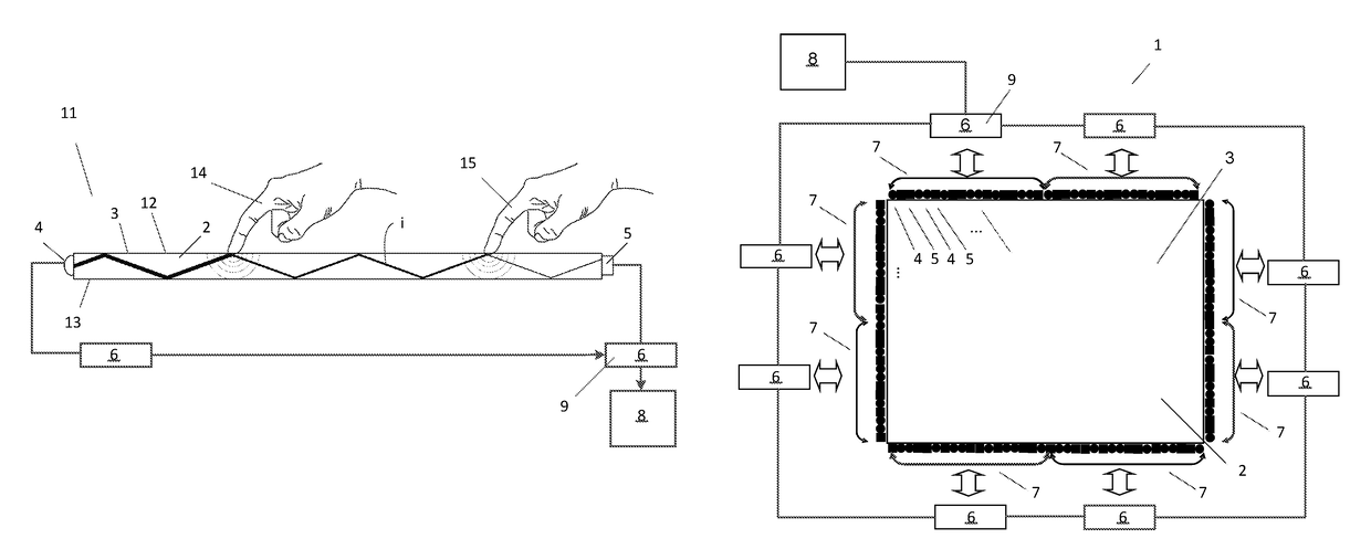
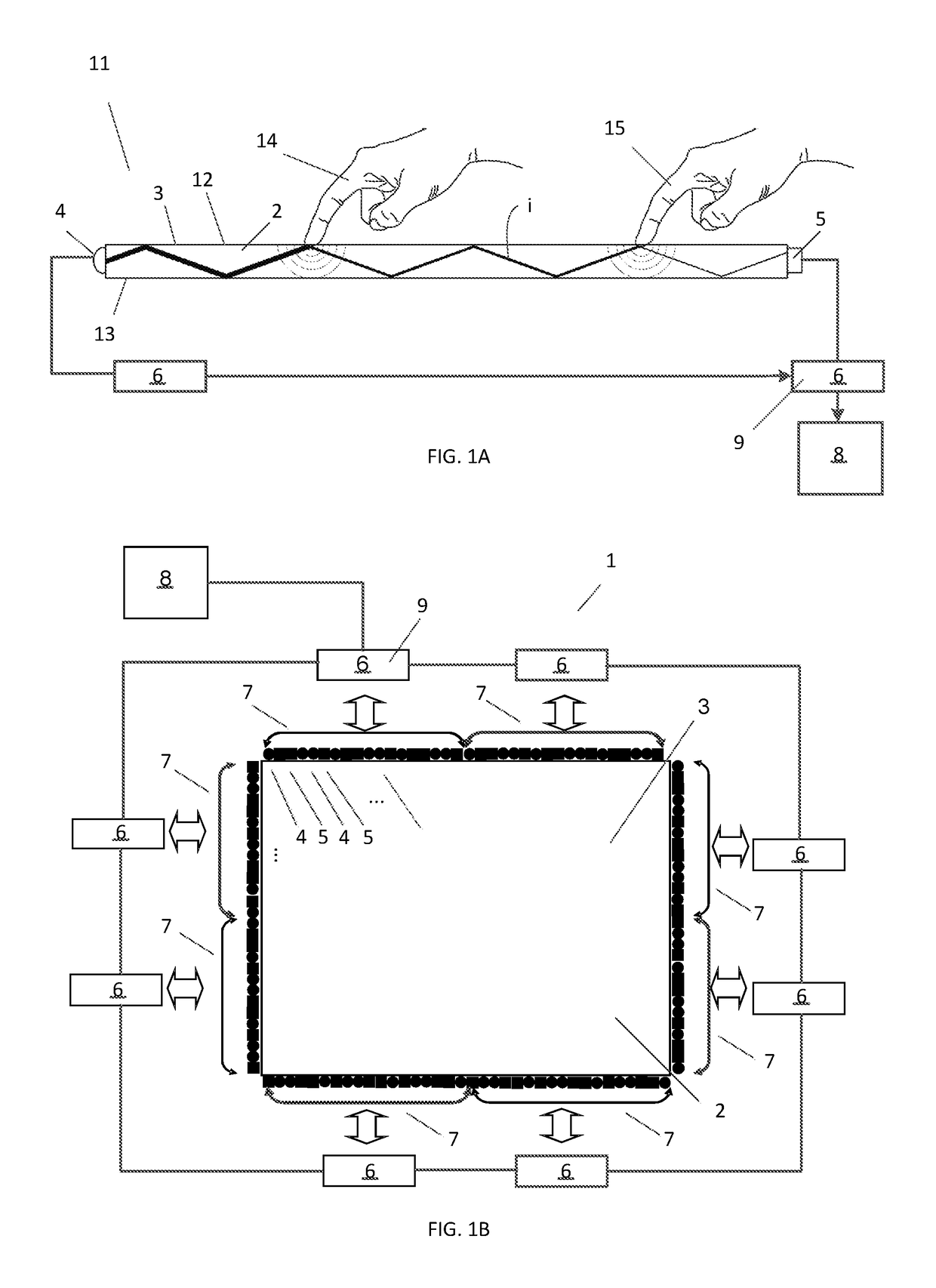
[0051]FIG. 1A-1B illustrates a side view and a top view of an example embodiment of a touch-sensitive system 1 that is based on the concept of FTIR (Frustrated Total Internal Reflection), also denoted “FTIR system”. The touch arrangement 11 operates by transmitting light inside a touch sensitive panel 2, from light emitters 4 to light sensors or detectors 5, so as to illuminate a touch surface 3 from within the panel 2. The panel 2 is made of solid material in one or more layers and may have any shape. The panel 2 defines an internal radiation propagation channel, in which light propagates by internal reflections. In the example of FIG. 1A, the propagation channel is defined between two boundary surfaces 12, 13 of the panel 2, where a top surface 12 allows the propagating light to interact with touching objects 14, 15 and thereby defines the touch surface 3. This is achieved by injecting the light into the panel 2 such that the light is reflected by total internal reflection (TIR) i...


PUM


Abstract

The disclosure relates to a touch sensitive system comprising a touch sensitive panel defining a touch surface, a plurality of emitters configured to emit light into the panel for propagation in the panel, a plurality of detectors configured to detect the light propagating in the panel, a plurality of distributed control devices each configured to control operation of a segment of emitters and detectors, a main control unit configured to control the distributed control devices. The touch sensitive system is configured to be set in a partial detect mode in which mode a first of the distributed control devices is configured to be active and to control a first emitter to emit light in a partial region of the panel coincident with a partial area of the touch surface. The touch sensitive system is further configured to detect a predetermined gesture on the partial area of the touch surface, generate a gesture signal indicating the predetermined gesture, and activate a feature of the touch sensitive system in accordance with the predetermined gesture. The disclosure also relates to a method in connection with the touch sensitive system.

Description

CROSS-REFERENCE TO RELATED APPLICATIONS[0001]The present application claims the benefit of Swedish patent application No. 1350870-0, filed 12 Jul. 2013.FIELD OF THE INVENTION[0002]The present invention relates to low power functions in a touch system to e.g. start up the system according to the preamble of the independent claim. In particular, the touch system includes distributed control devices configured to control emission and detection of light.BACKGROUND OF THE INVENTION[0003]Touch sensing systems (“touch systems”) are in widespread use in a variety of applications. Typically, the touch systems are actuated by a touch object such as a finger or stylus, either in direct contact, or through proximity (i.e. without contact), with a touch surface. Touch systems are for example used as touch pads of laptop computers, in control panels, and as overlays to displays on e.g. hand held devices, such as mobile telephones. A touch panel that is overlaid on or integrated in a display is al...

Claims


Application Information

Patent Timeline
Patent Type & Authority Patents(United States)
IPC IPC(8): G06F3/042G06F3/041G06F3/0488G06F1/32
CPCG06F3/0421G06F1/3262G06F1/3296G06F3/04883G06F3/0416G06F2203/04109G06F2203/04104G06F3/04166
Inventor WALL, HENRIK
Owner FLATFROG LAB
Why Eureka
Try Eureka