Systems and methods for evaluating component strain

a technology of component strain and component strain, which is applied in the direction of gas-turbine engine testing, machines/engines, instruments, etc., can solve the problems of reducing the usable life of components, creeping of various components within the turbomachine and particularly within the turbine section of the turbomachine, and unwanted vibrations

Active Publication Date: 2018-01-30
GENERAL ELECTRIC CO
View PDF45 Cites 74 Cited by
  • Summary
  • Abstract
  • Description
  • Claims
  • Application Information

AI Technical Summary

Problems solved by technology

Over time, an apparatus's individual components may suffer creep and / or deformation that may reduce the component's usable life.
During operation of a turbomachine, various components within the turbomachine and particularly within the turbine section of the turbomachine, such as turbine blades, may be subject to creep due to high temperatures and stresses.
For turbine blades, creep may cause portions of or the entire blade to elongate so that the blade tips contact a stationary structure, for example a turbine casing, and potentially cause unwanted vibrations and / or reduced performance during operation.
However, such deformation can in many cases be on the order of 0.01% of an original dimension, thus requiring specialized equipment for strain monitoring.
Such equipment in many cases requires precise calibrations which are not feasible in situ.
However, such approaches generally require a direct line of sight to the sensor and component.
As a result, in situ measurements can be difficult, if not impossible with most existing systems.

Method used


Image

  • Systems and methods for evaluating component strain
  • Systems and methods for evaluating component strain
  • Systems and methods for evaluating component strain

Examples


Embodiment Construction

[0027]Reference now will be made in detail to embodiments of the invention, one or more examples of which are illustrated in the drawings. Each example is provided by way of explanation of the invention, not limitation of the invention. In fact, it will be apparent to those skilled in the art that various modifications and variations can be made in the present invention without departing from the scope or spirit of the invention. For instance, features illustrated or described as part of one embodiment can be used with another embodiment to yield a still further embodiment. Thus, it is intended that the present invention covers such modifications and variations as come within the scope of the appended claims and their equivalents.

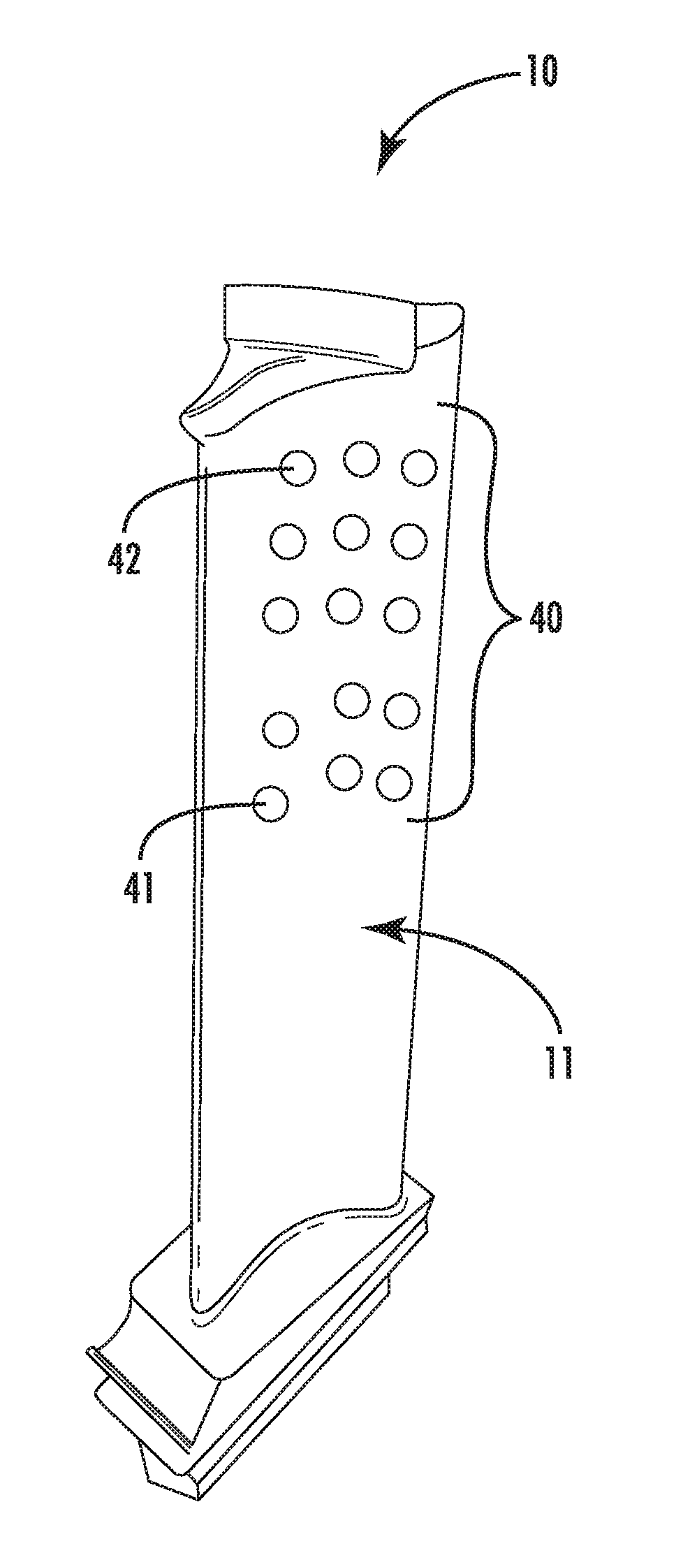
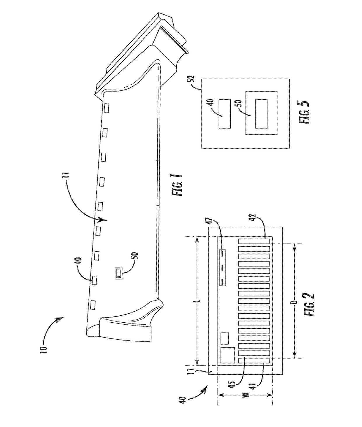
[0028]In accordance with one or more embodiments of the present subject matter, a component 10 having an exterior surface 11 with a reference feature 40 on the exterior surface 11 may be evaluated by forming a replicate 50 of the reference feature 40 at at ...


PUM

PropertyMeasurementUnit
widthaaaaaaaaaa
widthaaaaaaaaaa
thicknessaaaaaaaaaa

Abstract

A system and related methods for evaluating a component using a reference feature and a replicate of the reference feature. The component has an exterior surface with a reference feature thereon. The method includes determining an initial condition of the reference feature, subjecting the component to at least one duty cycle after determining the initial condition, determining a subsequent condition of the reference feature after the at least one duty cycle while the component is in a service position, and forming a replicate of the reference feature while the reference feature is in one of the initial condition or the subsequent condition. One of the initial condition or the subsequent condition may be determined based on the replicate of the reference feature.

Description

FIELD[0001]The present disclosure relates generally to systems and methods for evaluating component strain, and more particularly to systems and methods which permit measurements and scans of passive strain indicators positioned on the component while the component remains in a service position.BACKGROUND[0002]Throughout various industrial applications, apparatus components are subjected to numerous extreme conditions (e.g., high temperatures, high pressures, large stress loads, etc.). Over time, an apparatus's individual components may suffer creep and / or deformation that may reduce the component's usable life. Such concerns might apply, for instance, to some turbomachines.[0003]Turbomachines are widely utilized in fields such as power generation and aircraft engines. For example, a conventional gas turbine system includes a compressor section, a combustor section, and at least one turbine section. The compressor section is configured to compress air as the air flows through the co...

Claims


Application Information

Patent Timeline
Patent Type & Authority Patents(United States)
IPC IPC(8): G01N3/00G01B11/16G01M15/14G01M5/00
CPCG01B11/16G01M15/14F05B2270/808G01M5/00G01M5/0016G01M5/0041G01M5/0091
Inventor DEHGHAN NIRI, EHSANBATZINGER, THOMAS JAMESHOVIS, GREGORY LEELUO, KEVINLOCHNER, CHRISTOPHER JOSEPH
Owner GENERAL ELECTRIC CO
Why Eureka
Try Eureka