Convection-free flow-type reactor and flow-type synthesis method

a flow-type reactor and flow-type technology, applied in the direction of energy-based chemical/physical/physical-chemical processes, chemical apparatus and processes, chemical/physical/physical-chemical processes, etc., can solve the problems of increasing processing time, manual labor and manufacturing costs, and long reaction time requirements

Active Publication Date: 2018-02-06
ACAD SINIC
View PDF5 Cites 0 Cited by
  • Summary
  • Abstract
  • Description
  • Claims
  • Application Information

AI Technical Summary

Benefits of technology

[0008]An exemplary embodiment of a convection-free flow-type reactor comprises a reactor body. The reactor body comprises a reaction chamber to house a fluid. An inlet communicates with the reaction chamber to allow input of a reactant fluid. An outlet communicates with the reaction chamber to allow output of a product fluid. An energy beam source device provides an energy beam to irradiate the reactant fluid in the reaction chamber.

Problems solved by technology

In conventional photochemical reactions, since irradiant energy such as ultraviolet light does not have sufficient transmission or intensity, the required reaction time is long, such as several minutes to several hours or longer.
However, in the batch reactions, the product after each reaction needs to be taken out in order to proceed with the next batch reaction, which results in an increase in processing time, manual labor and manufacturing cost.
In addition, batch reactions are more expensive and make it difficult to achieve high productivity.
However, as described above, the required reaction time for the conventional photochemical reactions is too long to be implemented by the flow-type reactions.
Moreover, uniformity of the conventional photochemical reactions may be poor, and does not facilitate controlling the properties of materials (e.g., particle size).

Method used


Image

  • Convection-free flow-type reactor and flow-type synthesis method
  • Convection-free flow-type reactor and flow-type synthesis method
  • Convection-free flow-type reactor and flow-type synthesis method

Examples


embodiment 1

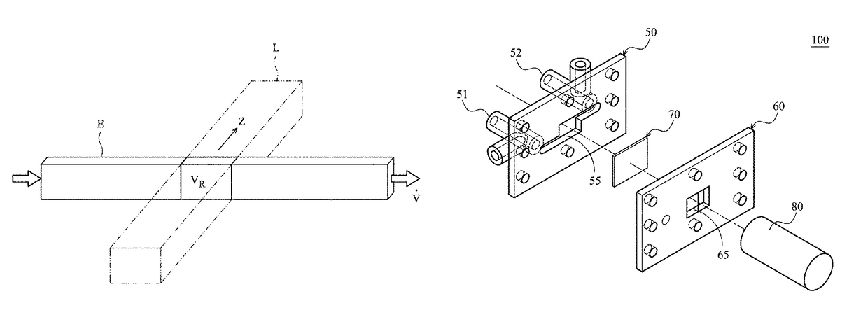
[0038]FIG. 5 illustrates a flow-type reactor 100 according to Embodiment 1. The flow-type reactor 100 substantially comprises four components, which are an aluminum reactor body 50, an aluminum cover 60, a polymide film 70 (i.e., an energy beam transmissible material) disposed between the aluminum reactor body 50 and the aluminum cover 60, and a synchrotron X-ray source 80. The aluminum reactor body 50 (first component) comprises an inlet 51, an outlet 52 and a cavity 55 (serving as a reactant loading space) in communication with the inlet 51 and the outlet 52. The aluminum cover 60 (second component) has a window 65 corresponding to the cavity 55, and the polymide film 70 is sandwiched between the cavity 55 and the window 65. The size of the polymide film 70 is not smaller than that of the window 65 to fully cover and seal the window 65.

[0039]The synchrotron X-ray source 80 is located about 20 cm away from the aluminum cover 60 having the window 65. The synchrotron X-ray has a dose...


PUM


Abstract

A convection-free flow-type reactor includes a reactor body. The reactor body includes a reaction chamber to house a fluid. An inlet is in communication with the reaction chamber to allow input of a reactant fluid. An outlet is in communication with the reaction chamber to allow output of a product fluid. An energy beam source device provides an energy beam to irradiate the reactant fluid in the reaction chamber. The disclosure further provides a convection-free flow-type synthesis method.

Description

CROSS REFERENCE TO RELATED APPLICATIONS[0001]This Application claims priority of Taiwan Patent Application No. 102123934, filed on Jul. 4, 2013, the entirety of which is incorporated by reference herein.BACKGROUND OF THE INVENTION[0002]Field of the Invention[0003]The invention relates to a flow-type reactor and a flow-type synthesis method using high-energy beam irradiation.[0004]Description of the Related Art[0005]In conventional photochemical reactions, since irradiant energy such as ultraviolet light does not have sufficient transmission or intensity, the required reaction time is long, such as several minutes to several hours or longer. Therefore, the reactions need to be batch reactions. However, in the batch reactions, the product after each reaction needs to be taken out in order to proceed with the next batch reaction, which results in an increase in processing time, manual labor and manufacturing cost. In addition, batch reactions are more expensive and make it difficult to...

Claims


Application Information

Patent Timeline
Patent Type & Authority Patents(United States)
IPC IPC(8): B01J19/12B01J19/02B01J19/00B01J19/08B01J4/00B01J19/24
CPCB01J19/125B01J19/0093B01J19/02B01J19/082B01J19/2415B01J4/002B01J2219/0877B01J2219/00164B01J2219/00799B01J2219/00801B01J2219/00822B01J2219/00833B01J2219/00927B01J2219/00939B01J2219/00959B01J2219/0277B01J2219/0295B01J2219/0871B01J19/0006B01J19/085B01J19/12B01J2219/00006
Inventor HWU, YEU-KUANGLAI, SHENG-FENGWANG, CHENG-LIANG
Owner ACAD SINIC
Why Eureka
Try Eureka