
Compressor areas for high overall pressure ratio gas turbine engine

Active Publication Date: 2018-02-20
RTX CORP
View PDF6 Cites 1 Cited by
  • Summary
  • Abstract
  • Description
  • Claims
  • Application Information

AI Technical Summary

Problems solved by technology

The downstream end of this high pressure compressor rotor is a challenging location within the gas turbine engine, as it must be able to withstand the temperatures and stresses it will see due to these high pressures.

Method used


Image

  • Compressor areas for high overall pressure ratio gas turbine engine
  • Compressor areas for high overall pressure ratio gas turbine engine

Examples


Embodiment Construction

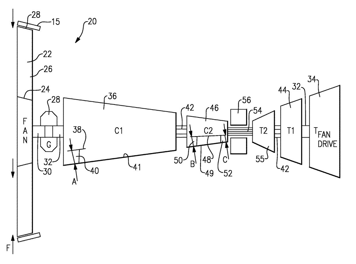
[0029]An engine 20 is illustrated in FIG. 1. A fan section 22 includes a hub 24 and radially outwardly extending blades 26 which extend to a radially outer end 28. A housing 15 encloses the blades 26.

[0030]A fan flow area F is defined between an outer periphery of the fan rotor 24 and inwardly of the outer tip 28.

[0031]A fan shaft 30 is driven through a gear reduction 28 by a shaft 32. The shaft 32 is, in turn, driven by a fan drive turbine rotor 34.

[0032]A low pressure compressor rotor 36 includes a hub 38 and radially outwardly extending blades 40. An upstream most of the blades defines a flow cross-sectional area A between an outer periphery of the hub 38 and an inner periphery 41 of an outer housing or an outer tip of the blade. A shaft 42 drives compressor rotor 36 and is, in turn, driven by an intermediate turbine rotor 44.

[0033]A high pressure compressor rotor 46 includes a hub 48 and an upstream most blade row 50. A flow cross-sectional area B is defined between an outer per...


PUM


Abstract

A gas turbine engine comprises a high pressure turbine rotor, an intermediate pressure turbine rotor and a fan drive turbine rotor. The fan drive turbine rotor drives a fan rotor through a gear reduction. The intermediate pressure rotor drives a low pressure compressor rotor and the high pressure turbine rotor drives a high pressure compressor rotor. A first flow cross-sectional area is between an outer periphery of a hub in the low pressure compressor rotor, and an outer tip of an upstream most blade row of the low pressure compressor rotor. A second flow cross-sectional area is between an outer periphery of a hub in the high pressure compressor rotor, and an outer tip of an upstream most blade row of the high pressure compressor rotor. A ratio of the first and second flow cross-sectional areas is greater than or equal to about 0.12 and less than or equal to about 0.33.

Description

CROSS-REFERENCE TO RELATED APPLICATION[0001]This application claims priority to U.S. Provisional Patent Application No. 61 / 947,502, filed Mar. 4, 2014.BACKGROUND OF THE INVENTION[0002]This application relates to the respective flow areas between a fan and a pair of compressor sections in a gas turbine engine having three turbine rotors.[0003]Gas turbine engines are known and, typically, include a fan delivering air into a compressor. The air is compressed in the compressor and delivered into a combustion section where it is mixed with fuel and ignited. Products of this combustion pass downstream over turbine rotors driving them to rotate.[0004]In one known type of gas turbine engine, there are three turbine rotors. A highest pressure turbine rotor and an intermediate pressure turbine rotor each drive compressor stages.[0005]The high pressure compressor rotor has typically been relied upon to develop a good deal of an overall pressure ratio across the two compressor rotors. The downs...

Claims


Application Information

Patent Timeline
Patent Type & Authority Patents(United States)
IPC IPC(8): F02C3/107F02C3/067F02C7/36
CPCF02C3/107F02C3/067F02C7/36F05D2260/4031F05D2250/44F04D19/028
Inventor SCHWARZ, FREDERICK M.PIXTON, STEPHEN G.
Owner RTX CORP
Learn More