Differential device
a technology of differential device and welded parts, which is applied in the direction of differential gearings, belts/chains/gearings, and differential gearings, etc., can solve the problems of deterioration in the durability of welded parts, and achieve the effect of reducing the assembling precision of the differential device as a whole, easing mechanical strain, and effectively preventing assembling precision
- Summary
- Abstract
- Description
- Claims
- Application Information
AI Technical Summary
Benefits of technology
Problems solved by technology
Method used
Image
Examples
first embodiment
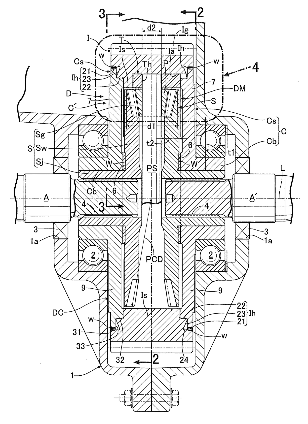
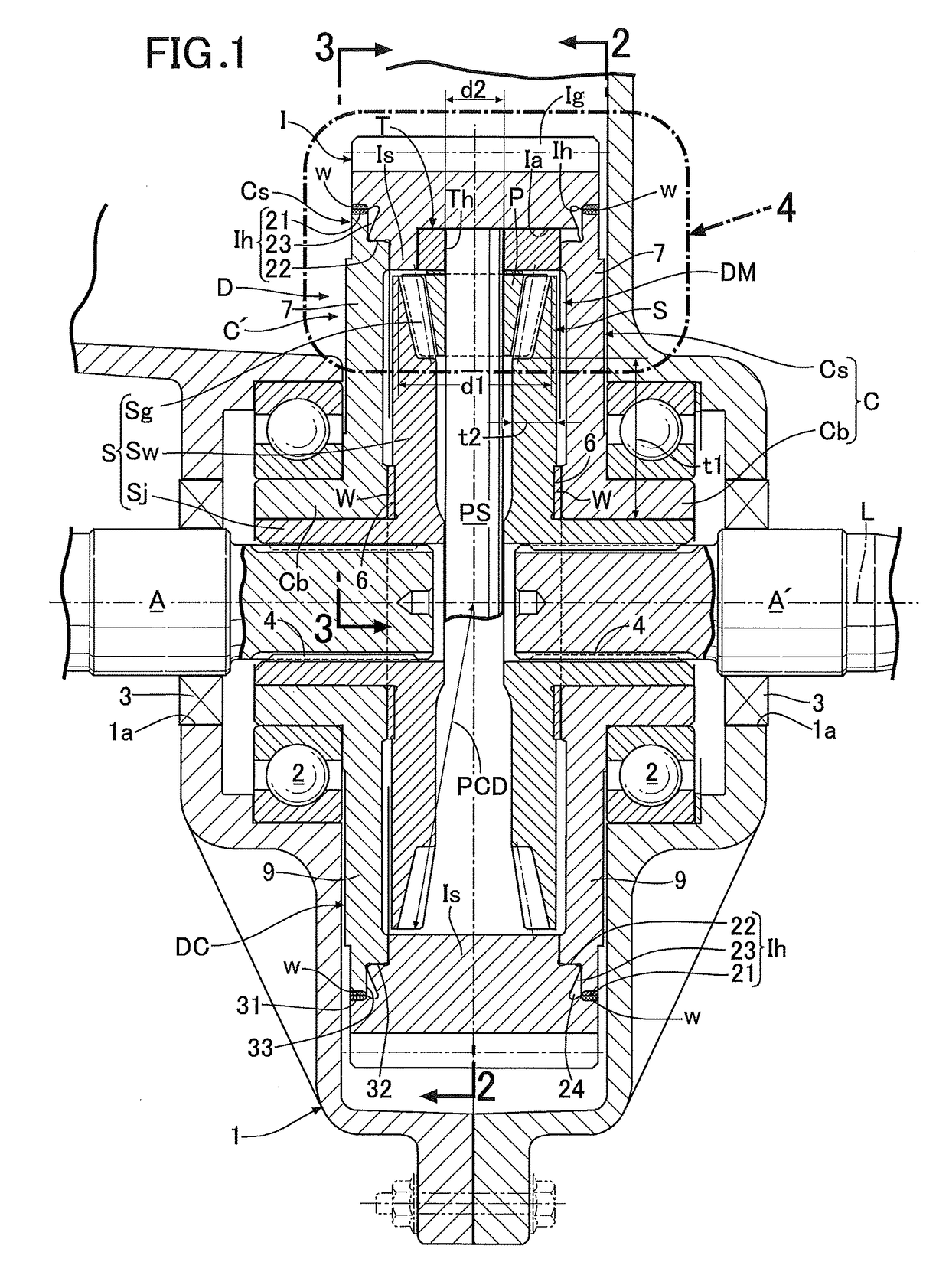
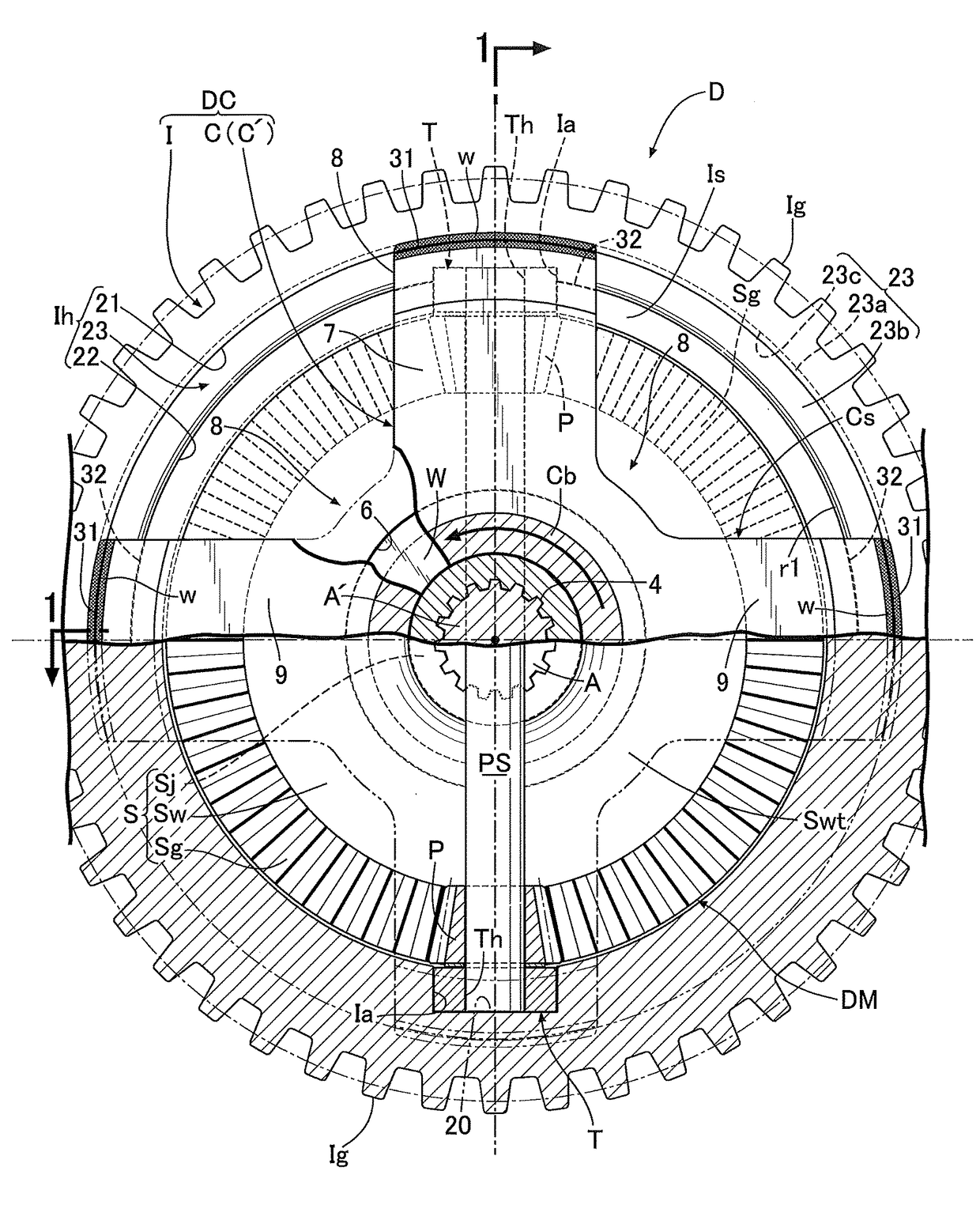
[0067]Next, descriptions will be provided for an operation of the In the differential device D of this embodiment, in a case where the input member I receives rotational force from the engine, when the pinion P revolves around the axis L of the input member I together with the input member I without rotating around the pinion shaft PS, the left and right side gears S are rotationally driven at the same speed, and their driving forces are evenly transmitted to the left and right output shafts A, A′. Meanwhile, when a difference in rotational speed occurs between the left and right output shafts A, A′ due to turn traveling or the like of the automobile, the pinion P revolves around the axis L of the input member I while rotating around the pinion shaft PS. Thereby, the rotational driving force is transmitted from the pinion P to the left and right side gears S while allowing differential rotations. The above is the same as the operation of the conventional differential device.
[0068]I...
second embodiment
[0079]Moreover, in this second embodiment, a bearing bush 12 as a bearing allowing relative rotations between the support shaft portion PS' and the attachment body T is inserted between an outer peripheral surface of the support shaft portion PS' and an inner peripheral surface of the retaining hole Th of the corresponding attachment body T into which the support shaft portion PS' is inserted. Incidentally, the bearing may be formed from a needle bearing or the like. In addition, the bearing may be omitted so that the support shaft portion PS' is directly fitted into the retaining hole Th of the attachment body T.
[0080]Next, referring to FIGS. 7 and 8, a third embodiment of the present invention will be described. A differential case DCX and a differential mechanism DMX housed inside the differential case DCX of the third embodiment are different in concrete structure and function from the differential case DC and the differential mechanism DM of the first and second embodiments.
[00...
third embodiment
[0086]Next, descriptions will be provided for an operation of the differential mechanism DMX of the differential device D of the For example, when temporarily fixing the input member I (the first rotary member) and rotating the one output shaft A, the main shaft portion 105a of the eccentric shaft 105 rotates and the second rotary member 106 in mesh with the inner teeth Ib of the input member I revolves around the first rotation axis X1 while rotating on the first eccentric shaft portion 105b. Meanwhile, the eccentric shaft 105 makes the second rotary member 106 and the third rotary member 107 revolve with the 180-degree phase shift therebetween, and the rotation of the second rotary member 106 is transmitted to the third rotary member 107 via the fourth rotary member 108. For these reasons, the revolution and the rotation of the second rotary member 106 is transmitted to the third rotary member 107 only by the 180-degree phase shift between the second rotary member 106 and the thi...
PUM
 Abstract
Description
Claims
Application Information
 - R&D
- Intellectual Property
- Life Sciences
- Materials
- Tech Scout
- Unparalleled Data Quality
- Higher Quality Content
- 60% Fewer Hallucinations
Browse by: Latest US Patents, China's latest patents, Technical Efficacy Thesaurus, Application Domain, Technology Topic, Popular Technical Reports.
© 2025 PatSnap. All rights reserved.Legal|Privacy policy|Modern Slavery Act Transparency Statement|Sitemap|About US| Contact US: help@patsnap.com


