Sensor module and method for producing sensor module

a technology of sensor module and sensor module, which is applied in the direction of instruments, semiconductor devices, measurement devices, etc., can solve the problems of complex process for output adjustment, exceed or fall short of a designed value, etc., and achieve the effect of easy output adjustmen

Active Publication Date: 2018-02-27
NAGANO KEIKI
View PDF6 Cites 0 Cited by
  • Summary
  • Abstract
  • Description
  • Claims
  • Application Information

AI Technical Summary

Benefits of technology

[0017]An object of the invention is to provide a sensor module with small variations in outputs of a plurality of strain gauges and capable of easily performing an output adjustment, and a method for producing the sensor module.
[0020]Since the electric conductor is arranged so that the linear portion of the resistor element connector exposed from the electric conductor is orthogonal to the edge of the electric conductor extending across the linear portion, even when the pattern is misaligned in the orthogonal direction with respect to the resistor element connector, the sum of the area of the strain gauge and the area of the part of the resistor element connector exposed from the electric conductor does not change, thereby keeping the resistances of the plurality of strain gauges from being changed. Accordingly, variation in the outputs of the plurality of strain gauges can be reduced, thereby facilitating the output adjustment.
[0022]According to the above arrangement, even when the pattern of the electric conductor may be misaligned in parallel to the linear portion in forming the electric conductor. Even when one of the resistor element connectors connected to both ends of the strain gauge becomes smaller than a designed value, the area of the other of the resistor element connectors becomes larger than the designed value, thereby compensating the increase and decrease in the areas. Accordingly, since the areas of the strain gauge and the resistor element connector stays the same irrespective of the pattern misalignment with the pattern of the electric conductor, the resistances of the plurality of strain gauges do not change. Consequently, the variation in the outputs of the plurality of strain gauges can be further reduced.
[0026]According to the above arrangement, since the strain gauge and the resistor element connector can be provided on the diaphragm in the same process, the production process can be simplified.

Problems solved by technology

However, when the pattern of the resistor element and the pattern of the conductor are misaligned with each other, the areas of the plurality of resistor elements exceed or fall short of a designed value.
The variation of the output of the resistor elements is unfavorable and thus an output adjustment of the resistor elements is required.
However, the output adjustment requires complicated processes.

Method used


Image

  • Sensor module and method for producing sensor module
  • Sensor module and method for producing sensor module
  • Sensor module and method for producing sensor module

Examples


first exemplary embodiment

[0045]FIGS. 1 to 3C show a first exemplary embodiment of the invention.

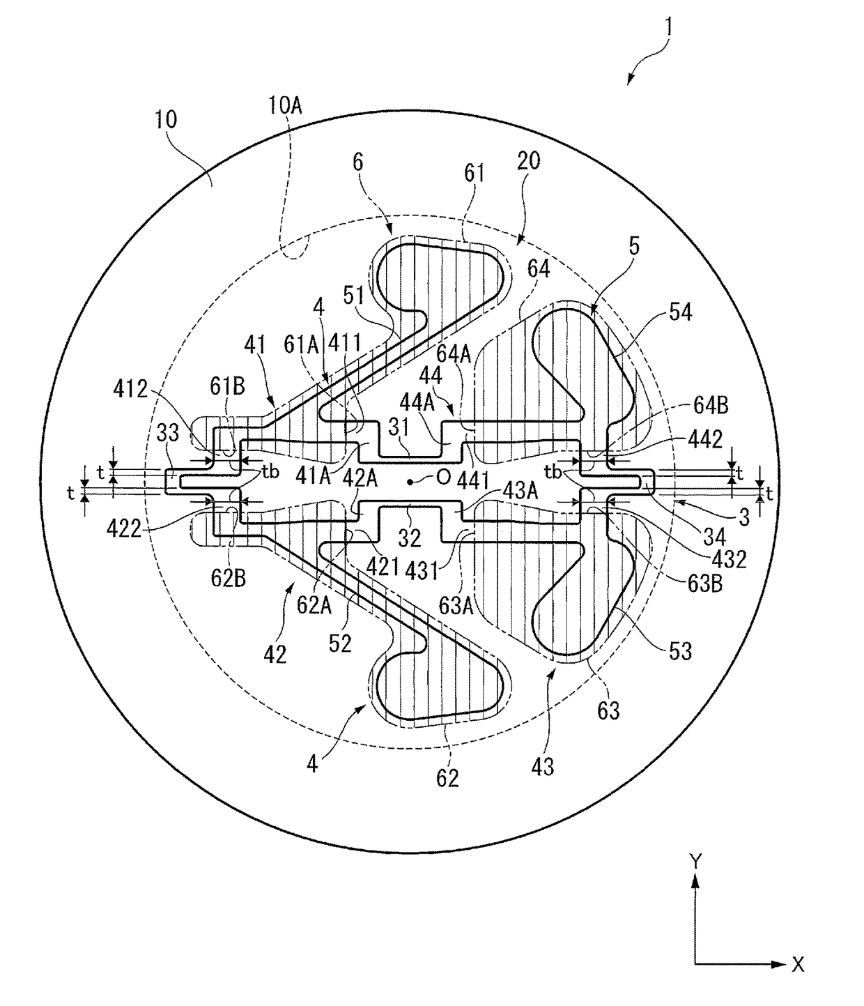
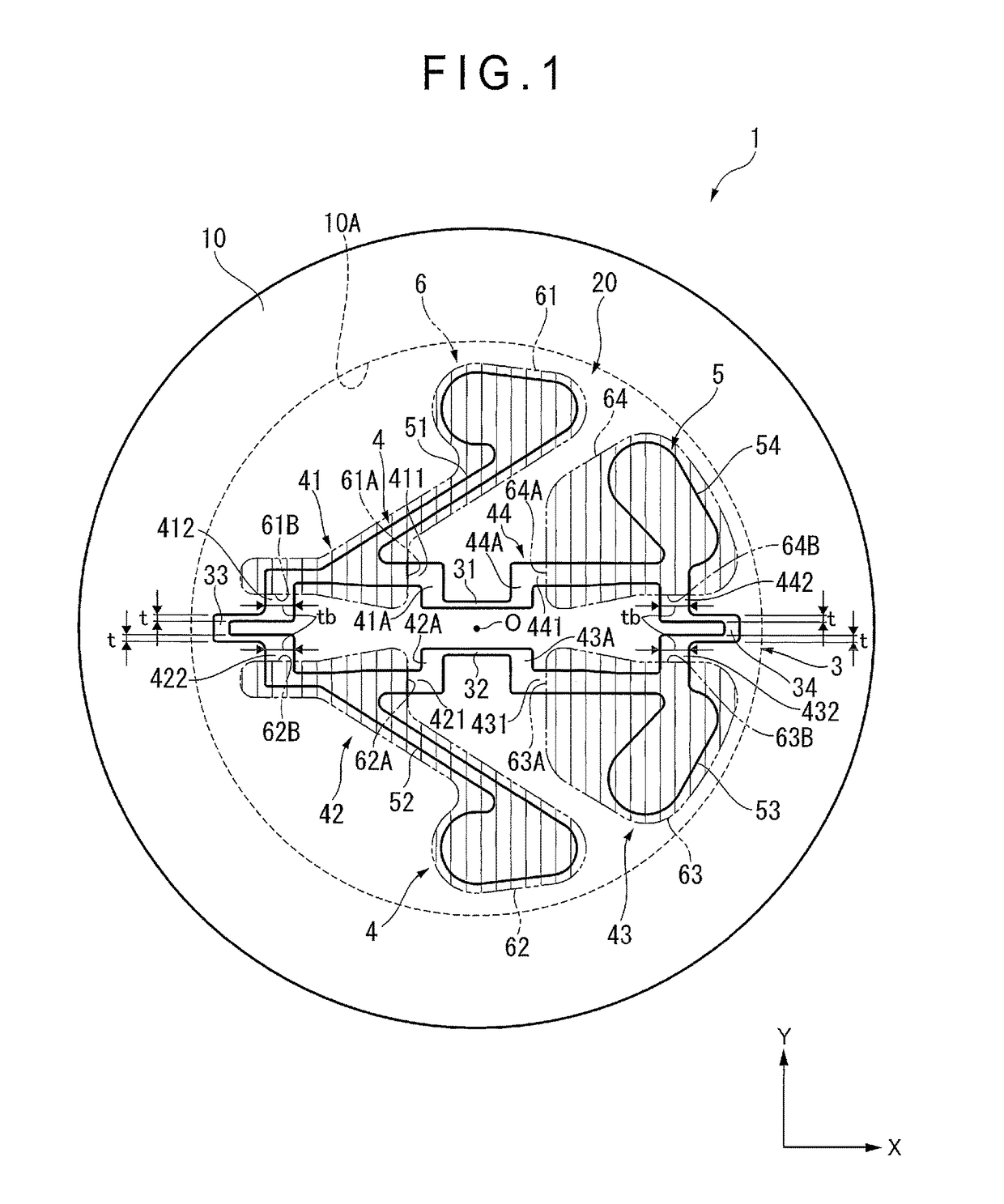
[0046]FIG. 1 shows an entire arrangement of a sensor module 1 in a plan view.

[0047]As shown in FIG. 1, the sensor module 1 includes a circular (in the plan view) diaphragm 10, and a detector 20 provided on a flat portion of the diaphragm 10 to detect a pressure.

[0048]The sensor module 1 of the exemplary embodiment is a pressure sensor device, in which the diaphragm 10 is displaced by a pressure of a to-be-measured fluid and the displacement of the diaphragm 10 is detected by the detector 20.

[0049]The diaphragm 10 is provided at an end of a cylindrical portion 10A. A recess, into which a to-be-measured fluid is introduced, is provided inside the cylindrical portion 10A. The diaphragm 10 and the cylindrical portion 10A are integrally provided using a metal material and the like. An insulation film (not shown) is provided on the flat portion of the diaphragm 10. The detector 20 is provided on the surface of the insu...

second exemplary embodiment

[0126]Next, the second exemplary embodiment of the invention will be described below with reference to FIGS. 4 to 5C.

[0127]The arrangement of the second exemplary embodiment is the same as that of the first exemplary embodiment except for the shape of the detector in a plan view. In the description of the second exemplary embodiment, the same numeral will be attached to the same components as those in the first exemplary embodiment to omit or simplify the description thereof.

[0128]FIG. 4 is a plan view showing a sensor module according to a second exemplary embodiment.

[0129]As shown in FIG. 4, a sensor module 2 includes the diaphragm 10, and a detector 20A provided on the flat portion of the diaphragm 10.

[0130]The detector 20A includes four strain gauges 7 for detecting a strain, the resistor element connector 8 connected with the strain gauges 7, the electrode 9 connected with the resistor element connector 8, and the electric conductor 100 covering a part of the resistor element c...

third exemplary embodiment

[0168]Next, the third exemplary embodiment of the invention will be described below with reference to FIG. 6.

[0169]The arrangement of the third exemplary embodiment is the same as that of the first exemplary embodiment except for the shape of the central strain gauge in a plan view. In the description of the third exemplary embodiment, the same numeral will be attached to the same components as those in the first exemplary embodiment to omit or simplify the description thereof.

[0170]FIG. 6 is a plan view showing a sensor module according to the third exemplary embodiment.

[0171]As shown in FIG. 6, a detector 20B of the third exemplary embodiment includes a strain gauge 35A.

[0172]The strain gauge 35A, the resistor element connector 4 and the electrode 5 are made of the same material (e.g. polysilicon).

[0173]The strain gauge 35A includes two central strain gauges 36, 37 disposed at the center of the diaphragm 10, and two outer strain gauges 33, 34 disposed at the outer side of the diap...


PUM

PropertyMeasurementUnit
electric currentaaaaaaaaaa

Abstract

A detector provided on a flat portion of a diaphragm includes a plurality of strain gauges, resistor element connectors connecting adjacent ones of the strain gauges, and an electric conductor covering a part of the resistor element connectors. First linear portions and second linear portions of the resistor element connectors exposed from the electric conductor are orthogonal to the edges of the electric conductor extending across the first linear portions and the second linear portions. Even when a pattern of the resistor element connector and a pattern of electric conductor are misaligned in X direction or in Y direction, an area of the resistor element connector exposed from the electric conductor does not change.

Description

[0001]The entire disclosure of Japanese Patent Application No. 2014-264220 filed Dec. 26, 2014 is expressly incorporated by reference herein.TECHNICAL FIELD[0002]The present invention relates to a sensor module and a method for producing the sensor module.BACKGROUND ART[0003]Some of the sensor modules of pressure sensors include a diaphragm, four strain gauges for detecting a strain, and resistor element connectors and electrodes connected to the strain gauges, the strain gauges, the resistor element connectors and the electrodes being provided on the diaphragm, where a part of each of the resistor element connectors and the electrodes are covered with an electric conductor.[0004]The electric conductor serves as a connector for the resistor element electrode, terminal(s) and the like and has a predetermined wiring pattern.[0005]In a typical thin-film pressure sensor, a silicon oxide layer, polysilicon layer and aluminum layer are deposited on a surface of a diaphragm, an aluminum-la...

Claims


Application Information

Patent Timeline
Patent Type & Authority Patents(United States)
IPC IPC(8): G01L9/00
CPCG01L9/0051G01L9/00H01L29/84
Inventor HATA, YUKIHIKOMIYASHITA, KAORITAKEDA, EIJI
Owner NAGANO KEIKI
Why Eureka
Try Eureka