
Palletizer, palletizing method, and transfer of a layer of objects by palletizer from a conveyor to a layer depositing tool

a technology of palletizer and layer, which is applied in the directions of stacking articles, transportation and packaging, packaging, etc., can solve the problems of high cost, synchronization, and slow and costly transfer, and achieve the effect of reducing the time and energy consumed in the palletization cycl

Active Publication Date: 2018-03-06
GEBO PACKAGING SOLUTIONS ITAL
View PDF13 Cites 3 Cited by
  • Summary
  • Abstract
  • Description
  • Claims
  • Application Information

AI Technical Summary

Benefits of technology

This patent describes a palletizer that uses a layer depositing tool to transfer objects from a conveyor onto a layer. The conveyor launches the preformed layer of objects with stored kinetic energy, which is transferred to the layer depositing tool to complete the transfer. This transfer is fast and inexpensive as it does not require synchronization with the conveyor. The palletizer can also have a braking mechanism for objects that slide easily on the surface of the conveyor or need to be quickly stopped for packing. The rollers in the layer depositing tool are not connected to a positive drive means, which reduces the weight and energy consumption of the tool.

Problems solved by technology

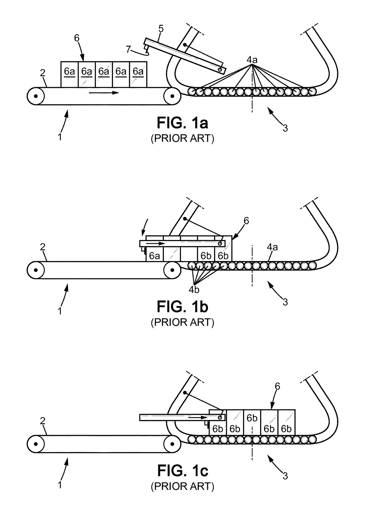
Such a method of transferring the objects from the conveyor 1 to the layer depositing tool 3 has several disadvantages which contribute to a slow and costly transfer.
This involves high costs and necessitates synchronization of the various means.
The disadvantage of this is that the layer depositing tool, which in this case is the fork, is immobilized for the entire duration of the formation of the layer to be palletized.
However, the transfer of a given object from the motor-driven rollers to the freely moving rollers is only completed because the objects following the given object, and advanced by the motorized rollers, push this object off the motorized rollers.

Method used


Image

  • Palletizer, palletizing method, and transfer of a layer of objects by palletizer from a conveyor to a layer depositing tool
  • Palletizer, palletizing method, and transfer of a layer of objects by palletizer from a conveyor to a layer depositing tool
  • Palletizer, palletizing method, and transfer of a layer of objects by palletizer from a conveyor to a layer depositing tool

Examples


Embodiment Construction

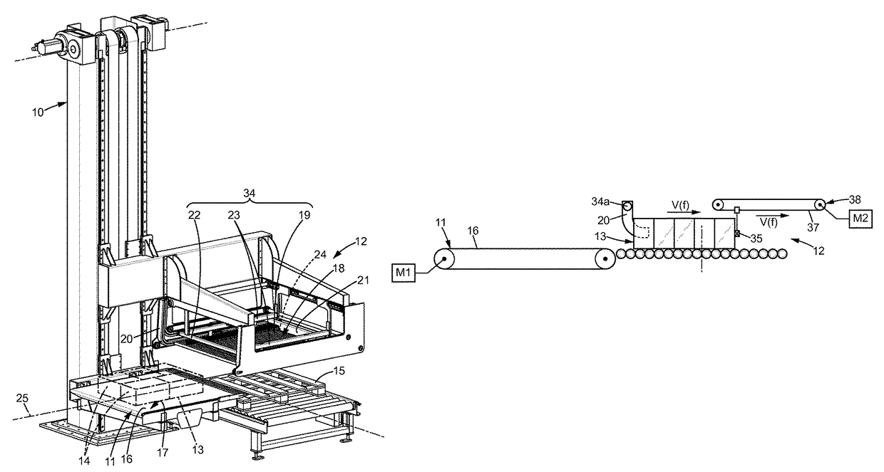
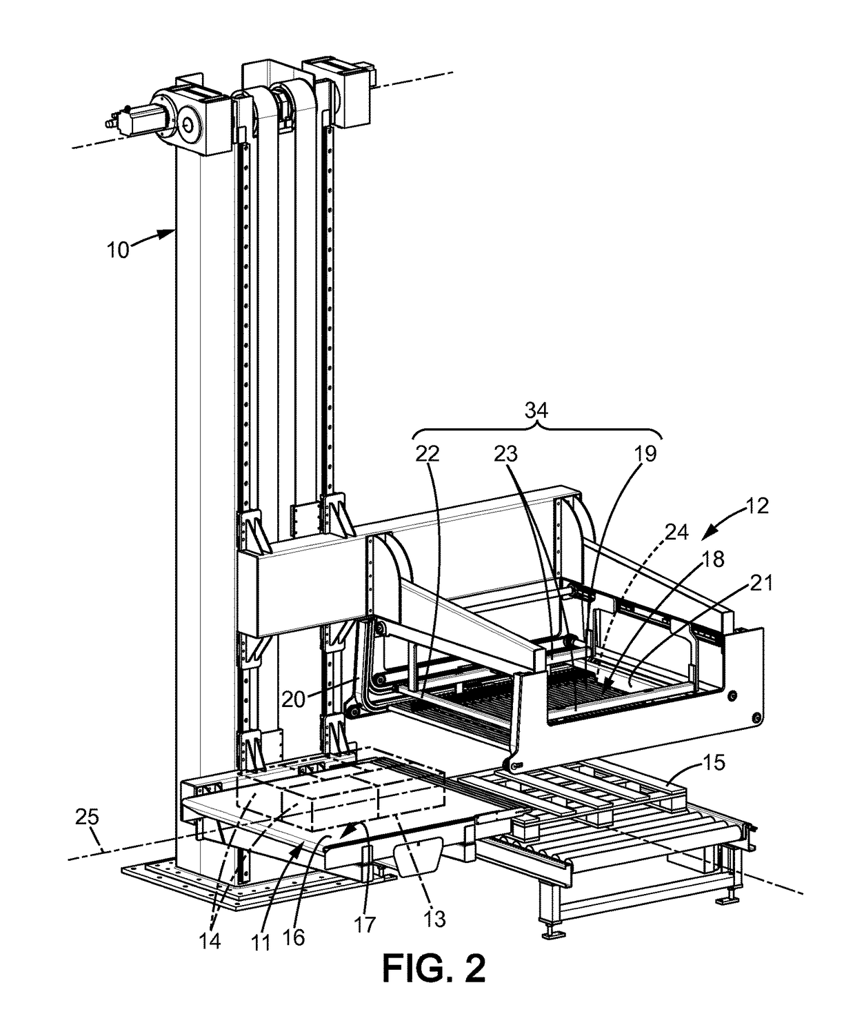
[0050]As illustrated in FIG. 2, the palletizer comprises a column 10 attached to the ground, on which a conveyor 11 and a layer depositing tool 12 slide vertically. Represented with dotted lines on the conveyor 11 is a layer 13 of objects 14 which have been previously assembled into the layer 13 by a layer preparation device which is not illustrated in these FIGURES. The objects 14 are, for example, packs of six bottles or any number of cans or parallelepiped cardboard containers. The pack is shrink-wrapped together in a film which gives it and maintains an external shape that is substantially parallelepiped. The layer 13 preparation device orients the objects 14 so that the layer 13 is compact and substantially covers the entire surface of a pallet 15. The layer depositing tool 12 is arranged above the pallet 15 and rises as the various layers 13 are stacked onto the pallet 15. The conveyor 11 primarily acts as a vertical shuttle between the layer preparation device and the layer d...


PUM


Abstract

A palletizer for depositing a preformed layer (13) of objects (14) on a pallet (15). The palletizer includes a conveyor, equipped with an advancement mechanism (16, M1), which advances the preformed layer of objects and is designed to impart kinetic energy to the preformed layer (13) of objects, a layer depositing tool (12) designed to deposit the preformed layer (13) of objects onto the pallet (15), and a transfer mechanism for transferring the preformed layer (13) of objects and designed so that the entirety of the preformed layer (13) of objects leaves the conveyor and arrives on the layer depositing tool (12). The transfer mechanism includes the advancement mechanism (16, M1). The conveyor is a conveyor-launcher (11) designed for launching the preformed layers (13) of objects, and the transfer mechanism includes the advancement mechanism of the conveyor-launcher and the kinetic energy imparted by the conveyor-launcher (11).

Description

FIELD OF THE INVENTION[0001]The invention relates to the field of palletizers and palletizing methods for depositing a preformed layer of objects on a pallet, particularly those which use a conveyor and a layer depositing tool.[0002]The invention particularly relates to the phase of transferring the preformed layer of objects from the conveyor to the layer depositing tool.RELATED ART[0003]FIGS. 1a to 1c of the present patent application illustrate a palletizer according to the preamble of claim 1 and a palletizing method according to the preamble of claim 11.[0004]The palletizer of FIGS. 1a to 1c comprises a conveyor 1 equipped with a motorized driving belt 2 and a layer depositing tool 3 that has a surface of freely rotating rollers 4 and is equipped with a transfer completion arm 5. The rollers 4 are for example mounted on bearings and are not driven by a motor. Some rollers 4a are rollers 4 which are not supporting objects and some rollers 4b have objects 6b rolling over them. Wh...

Claims


Application Information

Patent Timeline
Patent Type & Authority Patents(United States)
IPC IPC(8): B65G57/24B65B35/00
CPCB65B35/00B65G57/24
Inventor PETROVIC, ZMAJ
Owner GEBO PACKAGING SOLUTIONS ITAL
Learn More