Uptower wind turbine component replacement

a technology for wind turbines and components, applied in the direction of bearing repair/replacement, bearing rigid support, final product manufacturing, etc., can solve the problems of self-difficulty and costly installation, additional time and expense,

Active Publication Date: 2018-03-06
INVENTUS HLDG
View PDF17 Cites 7 Cited by
  • Summary
  • Abstract
  • Description
  • Claims
  • Application Information

AI Technical Summary

Problems solved by technology

The process of removing the entire drive train assembly requires a large crane, which is itself difficult and costly to install.
Additional time and expense is incurred by transporting the drive train assembly to an off-site location.

Method used


Image

  • Uptower wind turbine component replacement
  • Uptower wind turbine component replacement
  • Uptower wind turbine component replacement

Examples


Embodiment Construction

[0019]The following detailed description and the appended drawings describe and illustrate exemplary embodiments of the invention solely for the purpose of enabling one of ordinary skill in the relevant art to make and use the invention. As such, the detailed description and illustration of these embodiments are purely exemplary in nature and are in no way intended to limit the scope of the invention, or its protection, in any manner. It should also be understood that the drawings are not to scale and in certain instances details have been omitted, which are not necessary for an understanding of the present invention, such as conventional details of fabrication and assembly.

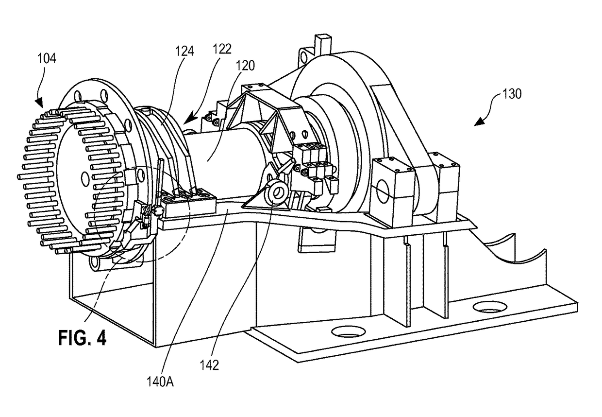
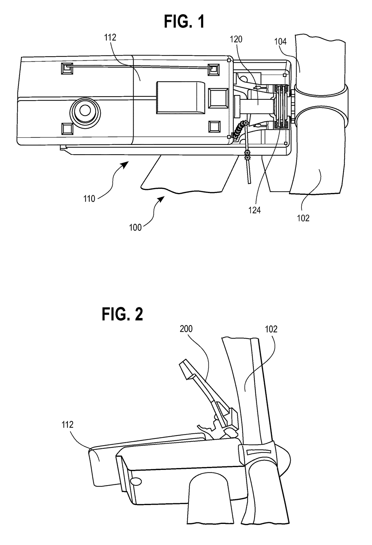
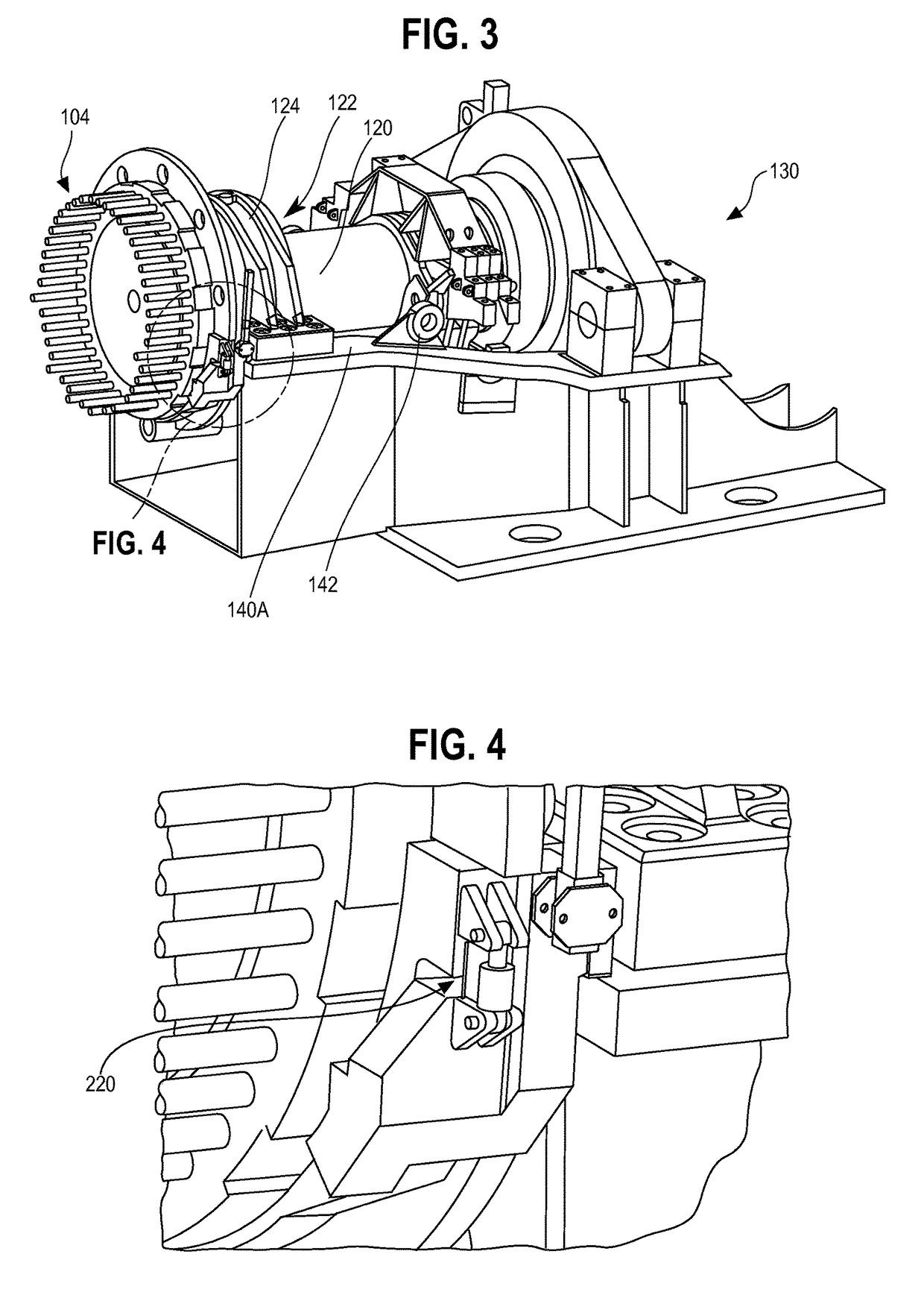
[0020]Where a turbine may include one or more turbine blades connected to a main shaft and a nacelle housing for enclosing components of the wind turbine including at least a portion of the main shaft and a main bearing, the main bearing fixable to a stationary position with respect to the main shaft by a main be...


PUM

PropertyMeasurementUnit
diameteraaaaaaaaaa
clearance heightaaaaaaaaaa
heightaaaaaaaaaa

Abstract

A method for performing uptower maintenance of a wind turbine in order to replace the main bearing on the turbine shaft is disclosed. Embodiments of this method to perform maintenance may include installing a rotor lock to resist rotation of the main shaft during maintenance, providing a lifting device in order to elevate the main shaft, removing the main bearing from its main bearing housing, and installing a replacement split main bearing. A crane may also be installed uptower to assist in the maintenance.

Description

CROSS REFERENCE TO RELATED APPLICATIONS[0001]This application claims the benefit of U.S. Provisional Application No. 61 / 886,985 filed Oct. 4, 2013, the disclosure of which is hereby incorporated herein by reference in its entirety.BACKGROUND[0002]Wind turbine technology is providing an ever-increasing proportion of the electrical energy generated in the United States and worldwide. Wind turbines transform kinetic energy, provided by a wind source, into mechanical energy, which may in turn be used to produce electricity. A typical wind turbine consists of an electrical generator mounted in a nacelle atop a tower that may be sixty (60) or more meters tall. The generator is powered by wind, which rotates the turbine blades, which are connected to a drive train assembly, the drive train assembly including a main shaft connected to the blades, a main shaft bearing, and a gear box which increases the shaft speed passed to the generator. Like the generator, the drive train assembly is usua...

Claims


Application Information

Patent Timeline
Patent Type & Authority Patents(United States)
IPC IPC(8): F03D1/00F03D80/70F03D80/50
CPCF03D80/70F03D80/50F05B2230/80F05B2240/50Y02B10/30Y02E10/726Y02P70/523Y10T29/49318Y02E10/721F16C35/06F16C35/062F16C33/60F16C2360/31F05B2260/31Y02E10/72Y02P70/50F05B2230/70F16C2226/12F16C2237/00
Inventor LOHAN, MARTIN E.FENGER, PER ESKEASHEIM, CHARLESGONZALEZ, MIGUEL A.BRAKE, DANIEL M.
Owner INVENTUS HLDG
Why Eureka
Try Eureka