Force measurement system that includes a force measurement assembly, a visual display device, and one or more data processing devices

a technology of force measurement and force assembly, applied in the field of force measurement systems, can solve the problems of difficult to accommodate conventional force measurement systems, occupy a considerable amount of floor space in the building, and conventional force measurement systems are not capable of effectively immersing the subject being tested in a virtual reality environmen

Active Publication Date: 2018-03-13
BERTEC
View PDF57 Cites 48 Cited by
  • Summary
  • Abstract
  • Description
  • Claims
  • Application Information

AI Technical Summary

Benefits of technology

[0024]In still a further embodiment, the virtual representation of the subject on the output screen of the at least one visual display device comprises an avatar controlled by one or more body gestures of the subject as detected by the force measurement assembly and a motion detection system.
[0025]In yet a further embodiment, the one or more data processing devices are further configured to compute a center of pressure for the subject as a function of the output forces and / or moments determined from the one or more signals of the force measurement assembly, and to control a movement of the virtual representation of the subject on the output screen of the at least one visual display device using the computed center of pressure.
[0026]In still a further embodiment, at least one of the following devices is further operatively coupled to the one or more data processing devices: (i) an eye position tracking device configured to track a position of one or more eyes of the subject, (ii) a head position tracking device configured to track a position of the head of the subject; and (iii) a pointing device configured to indicate an aiming direction of a body portion of the subject.
[0027]In yet a further embodiment, the one or more data processing devices are further configured to generate one or more virtual targets, to display the one or more virtual targets in the scene on the output screen of the at least one visual display device, and to determine whether a pointing direction of the subject determined using at least one of the eye position tracking device, the head position tracking device, and the pointing device coincides with the one or more virtual targets displayed on the output screen. When the pointing direction of the subject coincides with the one or more virtual targets displayed on the output screen, the one or more data processing devices are further configured to maintain a current rotational speed of the one or more rotatable treadmill belts. Conversely, when the pointing direction of the subject does not coincide with the one or more virtual targets displayed on the output screen, the one or more data processing devices are further configured to decrease the rotational speed of the one or more rotatable treadmill belts below the current rotational speed of the one or more rotatable treadmill belts.
[0028]In still a further embodiment, the one or more virtual targets that are generated by the one or more data processing devices and displayed on the output screen of the at least one visual display device comprise a plurality of targets spaced apart on the output screen of the at least one visual display device; and the one or more data processing devices are further configured to determine whether the subject sequentially points in respective directions of each of the plurality of targets.
[0029]In yet a further embodiment, the one or more data processing devices are further configured to control a navigation of a virtual representation of the subject on the output screen of the at least one visual display device in accordance with an output signal from at least one of the eye position tracking device, the head position tracking device, and the pointing device.

Problems solved by technology

Although, it is often difficult to accommodate conventional force measurement systems in the spaces of many buildings due to their expansive sizes.
For example, a force plate array, which is often used as part of a gait lab in a building, typically occupies a considerable amount of floor space in the building.
In addition to the difficulties associated with the space requirements for these systems, conventional force measurement systems are not capable of effectively immersing the subject being tested in a virtual reality environment, which may be used to simulate real-life scenarios that are encountered by the subject.

Method used


Image

  • Force measurement system that includes a force measurement assembly, a visual display device, and one or more data processing devices
  • Force measurement system that includes a force measurement assembly, a visual display device, and one or more data processing devices
  • Force measurement system that includes a force measurement assembly, a visual display device, and one or more data processing devices

Examples


first embodiment

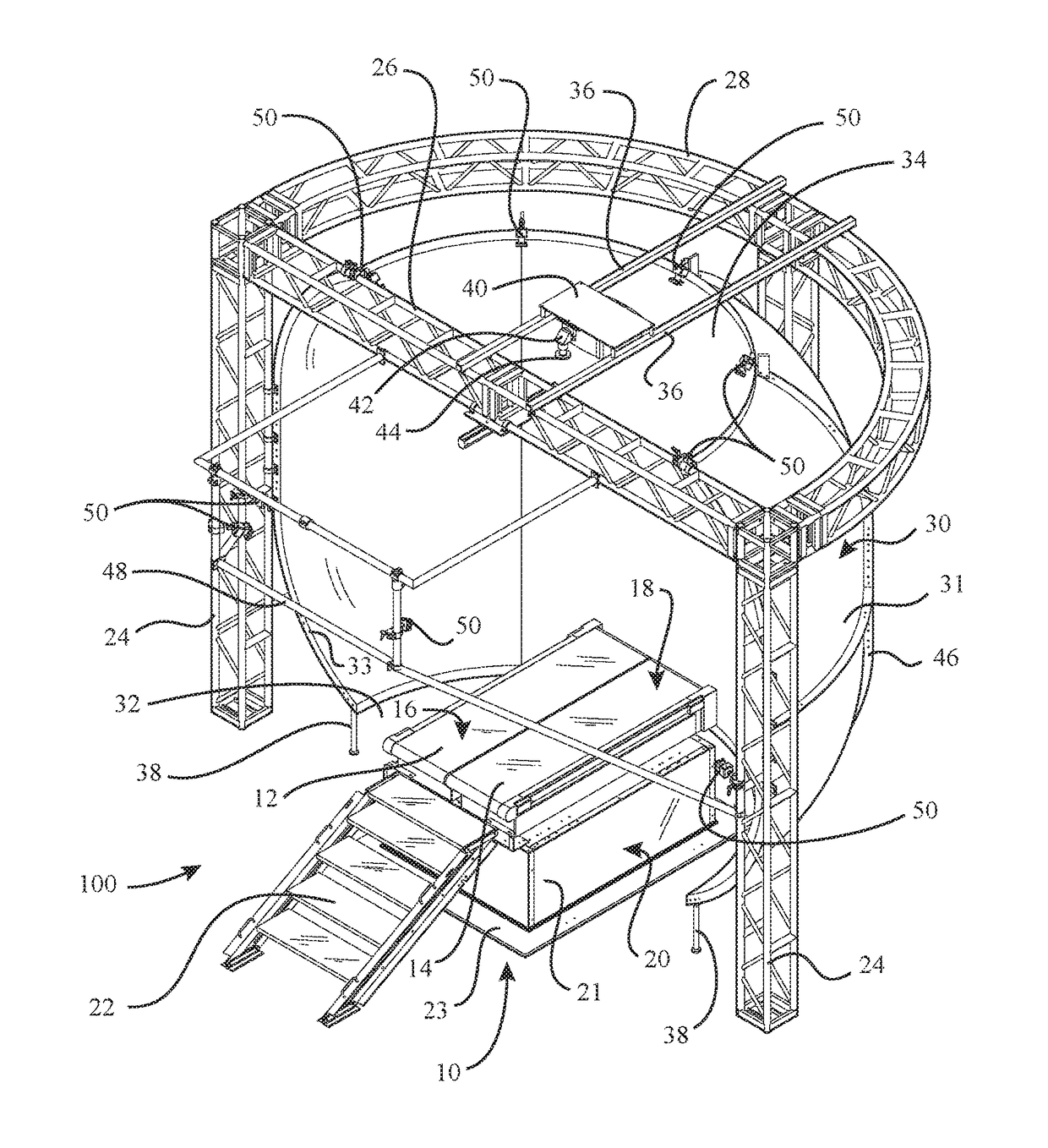
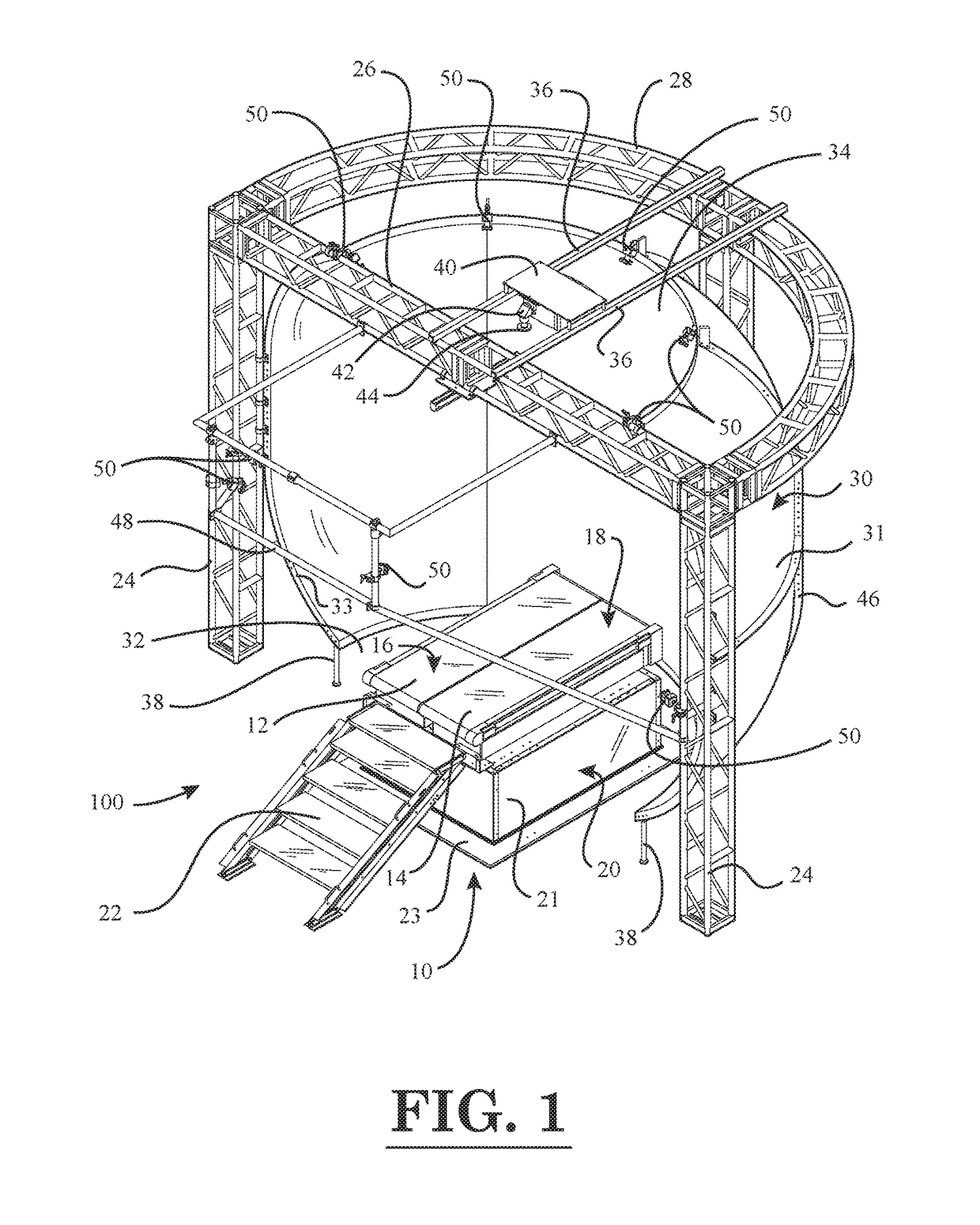
[0032]FIG. 1 is a perspective view of a force measurement system with a force measurement assembly in the form of an instrumented treadmill, according to the invention;

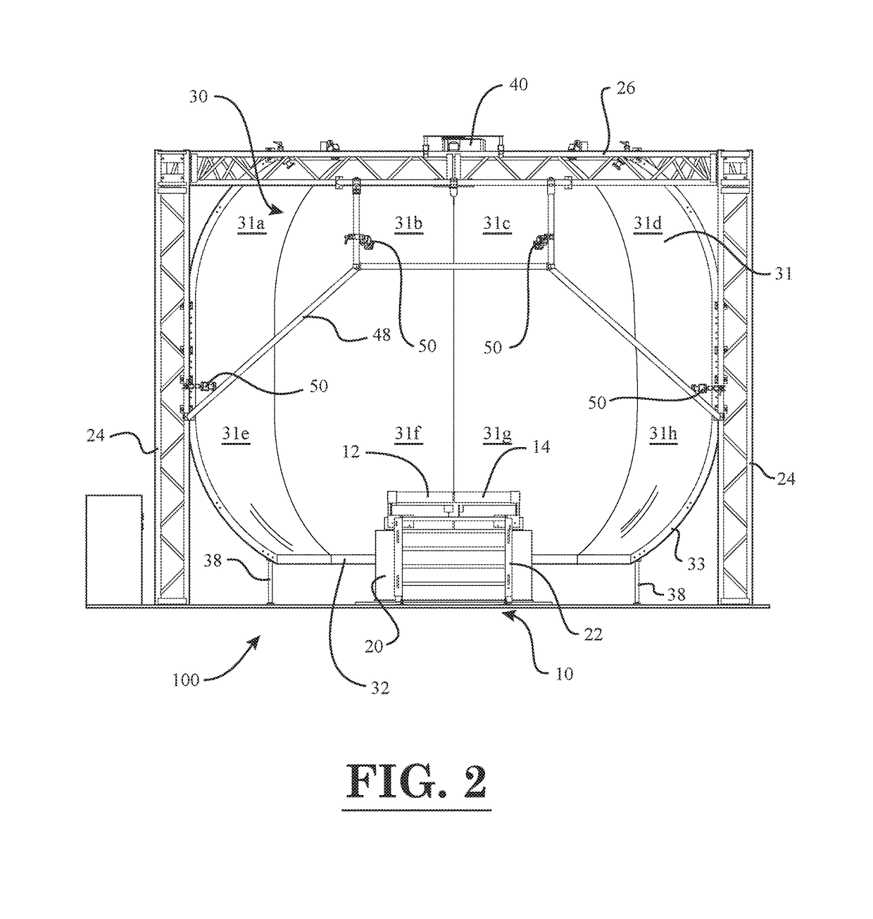
[0033]FIG. 2 is a front view of the force measurement system of FIG. 1;

[0034]FIG. 3 is a top view of the force measurement system of FIG. 1;

[0035]FIG. 4 is a side view of the force measurement system of FIG. 1;

second embodiment

[0036]FIG. 5 is a perspective view of a force measurement system with a force measurement assembly in the form of an instrumented treadmill, according to the invention;

[0037]FIG. 6 is a front view of the force measurement system of FIG. 5;

[0038]FIG. 7 is a perspective view of a concave projection screen of the force measurement systems of FIGS. 1 and 5;

[0039]FIG. 8 is a longitudinal sectional view of the concave projection screen of FIG. 7;

[0040]FIG. 9 is a block diagram of constituent components of the force measurement system with a force measurement assembly in the form of an instrumented treadmill, according to an embodiment of the invention;

[0041]FIG. 10 is a block diagram of the software and hardware architecture of the force measurement system with the force measurement assembly in the form of the instrumented treadmill;

[0042]FIG. 11 is a screen image of an immersive grocery aisle scene displayed on the output screen of the visual display device of the force measurement syste...


PUM

PropertyMeasurementUnit
depth DSaaaaaaaaaa
depth DSaaaaaaaaaa
angular field of viewaaaaaaaaaa

Abstract

A force measurement system includes a force measurement assembly with a top surface configured to receive at least one portion of the body of a subject and at least one force transducer configured to sense forces and/or moments being applied to the top surface; at least one visual display device having an output screen, the output screen comprising an overhanging top portion so that a top edge of the output screen is not readily visible to the subject; and one or more data processing devices operatively coupled to the force measurement assembly and the at least one visual display device. In one or more embodiments, the force measurement assembly may be in the form of an instrumented treadmill. In one or more further embodiments, the force measurement system may additionally comprise a motion capture system configured to detect the motion of one or more body gestures of the subject.

Description

CROSS-REFERENCE TO RELATED APPLICATIONS[0001]This patent application claims priority to, and incorporates by reference in its entirety, U.S. Provisional Patent Application No. 62 / 208,671, entitled “Force Measurement System”, filed on Aug. 22, 2015.STATEMENT REGARDING FEDERALLY SPONSORED RESEARCH OR DEVELOPMENT[0002]Not Applicable.NAMES OF THE PARTIES TO A JOINT RESEARCH AGREEMENT[0003]Not Applicable.INCORPORATION BY REFERENCE OF MATERIAL SUBMITTED ON A COMPACT DISK[0004]Not Applicable.BACKGROUND OF THE INVENTION1. Field of the Invention[0005]The invention generally relates to force measurement systems. More particularly, the invention relates to a force measurement system that is capable of immersing a subject in a virtual reality environment.2. Background and Description of Related Art[0006]Force measurement systems are utilized in various fields to quantify the reaction forces and moments exchanged between a body and support surface. For example, in biomedical applications, force ...

Claims


Application Information

Patent Timeline
Patent Type & Authority Patents(United States)
IPC IPC(8): A61B5/103G06F3/01A63B71/06A63B24/00G06F3/00H04N5/247G01L5/16
CPCG06F3/017G01L5/16H04N5/247G06F3/005G06F3/013G06F3/012A63B71/0622A63B24/0087A63B2071/0647A63B2024/009A63B2220/56A63B2220/51A63B22/0235A63B2024/0096A63B2071/0081A63B2071/0638A63B2071/0644A63B2220/53A63B2220/54A63B2220/80A63B2220/803A63B2220/806A63B2220/833A63B2225/093A63B2225/50A63F13/211A63F13/212A63F13/218A63F13/24A63F13/25A63F13/5255A63F13/90G06F3/011
Inventor BERME, NECIPBARNES, SCOTT ZERKLEHOFFMAN, BENJAMIN ROBERTGHASSAB, SASANPITALE, JASWANDI TUSHAR
Owner BERTEC
Why Eureka
Try Eureka