Force management system that includes a force measurement assembly, a visual display device, and one or more data processing devices

a technology of force management and force measurement, applied in the field of force measurement systems, can solve the problems of difficult to accommodate conventional force measurement systems, occupy a considerable amount of floor space in the building, and conventional force measurement systems are not capable of effectively immersing the subject being tested in a virtual reality environment, so as to facilitate the subject's proper focus

Active Publication Date: 2019-02-26
BERTEC
View PDF73 Cites 45 Cited by
  • Summary
  • Abstract
  • Description
  • Claims
  • Application Information

AI Technical Summary

Benefits of technology

[0024]In accordance with one or more other embodiments of the present invention, there is provided a force measurement system comprising a force measurement assembly configured to receive a subject, the force measurement assembly including one or more displaceable components, the one or more displaceable components having one or more respective surfaces for receiving one or more respective limbs of the subject; and at least one force transducer, the at least one force transducer configured to sense one or more measured quantities and output one or more signals that are representative of one or more loads being applied to the one or more respective surfaces of the one or more displaceable components by the subject; at least one visual display device having an output screen, the at least one visual display device configured to display a scene on the output screen so that the scene is viewable by the subject; a pointing or gaze direction determination device configured to determine a pointing direction or gaze direction of the subject, the pointing or gaze direction determination device being external to the at least one visual display device; and one or more data processing devices operatively coupled to the at least one force transducer of the force measurement assembly, the at least one visual display device, and the pointing or gaze direction determination device, the one or more data processing devices configured to receive the one or more signals that are representative of the forces and / or moments being applied to the one or more respective surfaces of the one or more displaceable components by the subject, and to convert the one or more signals into output forces and / or moments, the one or more data processing devices further configured to generate at least a first visual element and a second visual element, and to display the first visual element and the second visual element in the scene on the output screen of the at least one visual display device, the one or more data processing devices additionally configured to control the displacement of the one or more displaceable components of the force measurement assembly in accordance with the first visual element of the scene that is displayed on the output screen of the at least one visual display device, the one or more data processing devices further configured to determine a manner in which the subject interacts with the second visual element of the scene and to adjust the displacement of the one or more displaceable components of the force measurement assembly based upon the interaction of the subject with the second visual element during a subject testing or training routine, the second visual element of the scene that is displayed on the output screen of the at least one visual display device comprising at least one virtual target, and the one or more data processing devices additionally configured to determine the manner in which the subject interacts with the second visual element of the scene by determining when the pointing direction or the gaze direction of the subject, as determined by the pointing or gaze direction determination device, coincides with the at least one virtual target displayed on the output screen, and when the pointing direction of the subject does not coincide with the at least one virtual target displayed on the output screen. In these one or more other embodiments, when the pointing direction of the subject coincides with the at least one virtual target displayed on the output screen during the subject testing or training routine, the one or more data processing devices are further configured to maintain a current speed of the one or more displaceable components of the force measurement assembly. Also, in these one or more other embodiments, when the pointing direction of the subject does not coincide with the at least one virtual target displayed on the output screen during the subject testing or training routine, the one or more data processing devices are further configured to decrease the speed of the one or more displaceable components of the force measurement assembly below the current speed of the one or more displaceable components of the force measurement assembly so as to make it easier for the subject to properly focus on the at least one virtual target during the subject testing or training routine.

Problems solved by technology

Although, it is often difficult to accommodate conventional force measurement systems in the spaces of many buildings due to their expansive sizes.
For example, a force plate array, which is often used as part of a gait lab in a building, typically occupies a considerable amount of floor space in the building.
In addition to the difficulties associated with the space requirements for these systems, conventional force measurement systems are not capable of effectively immersing the subject being tested in a virtual reality environment, which may be used to simulate real-life scenarios that are encountered by the subject.

Method used


Image

  • Force management system that includes a force measurement assembly, a visual display device, and one or more data processing devices
  • Force management system that includes a force measurement assembly, a visual display device, and one or more data processing devices
  • Force management system that includes a force measurement assembly, a visual display device, and one or more data processing devices

Examples


first embodiment

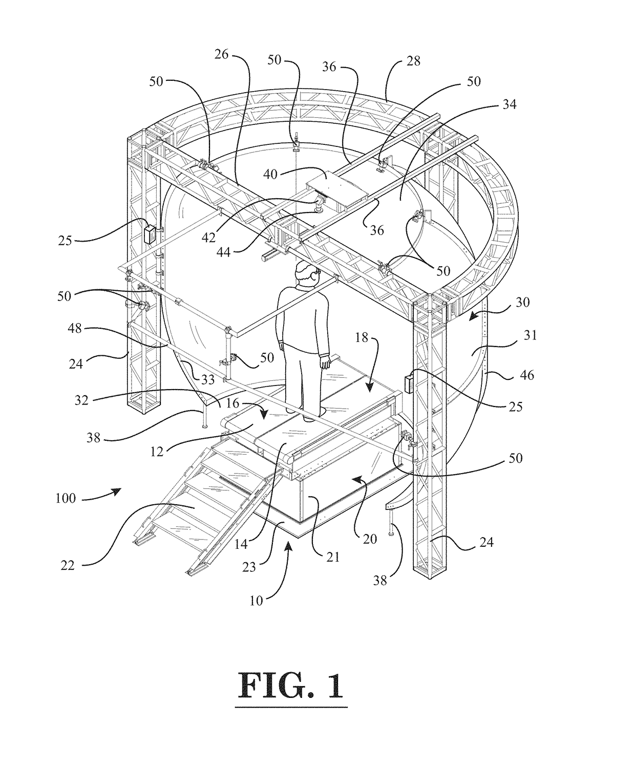
[0037]FIG. 1 is a perspective view of a force measurement system with a force measurement assembly in the form of an instrumented treadmill, according to the invention;

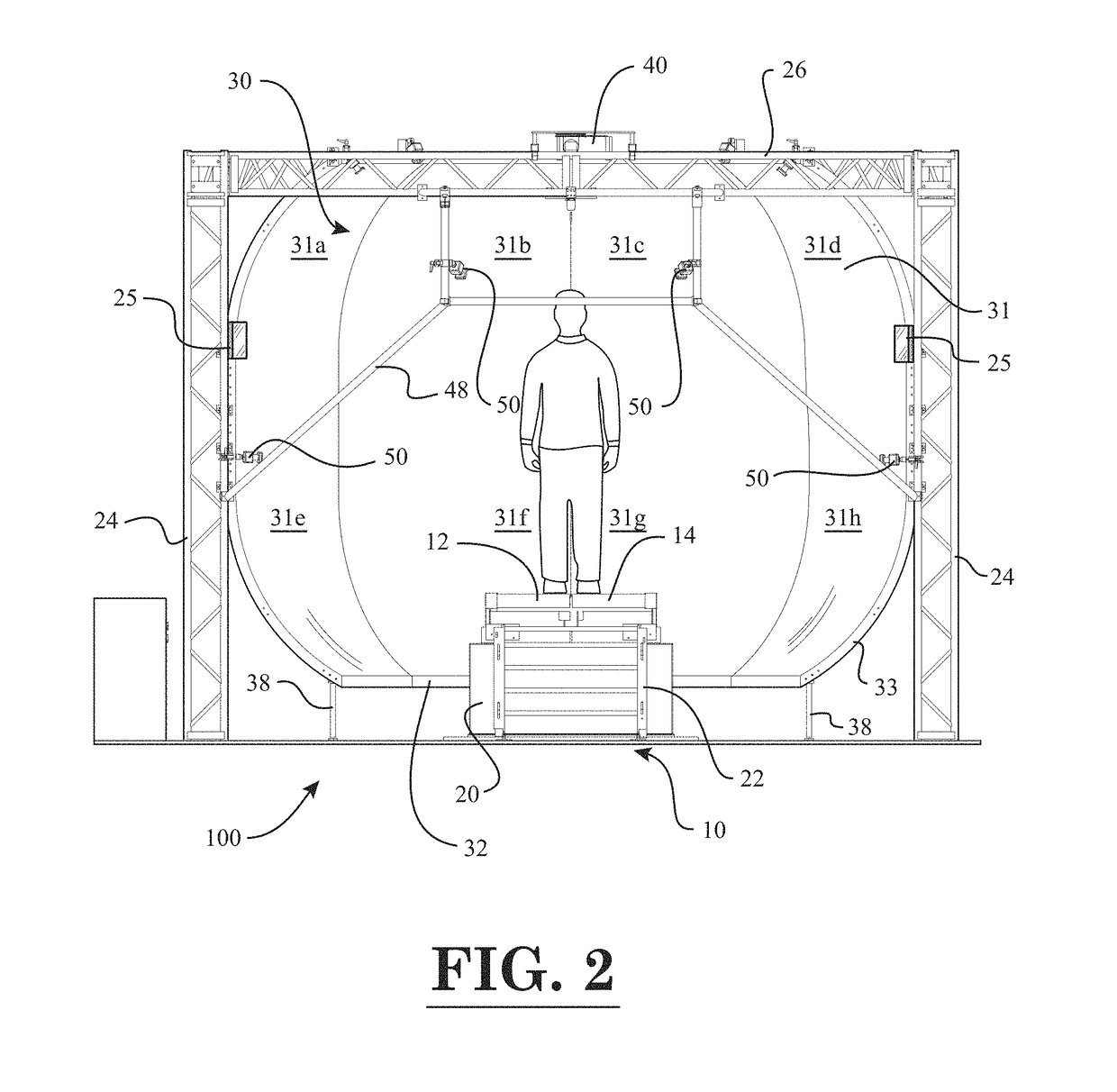
[0038]FIG. 2 is a front view of the force measurement system of FIG. 1;

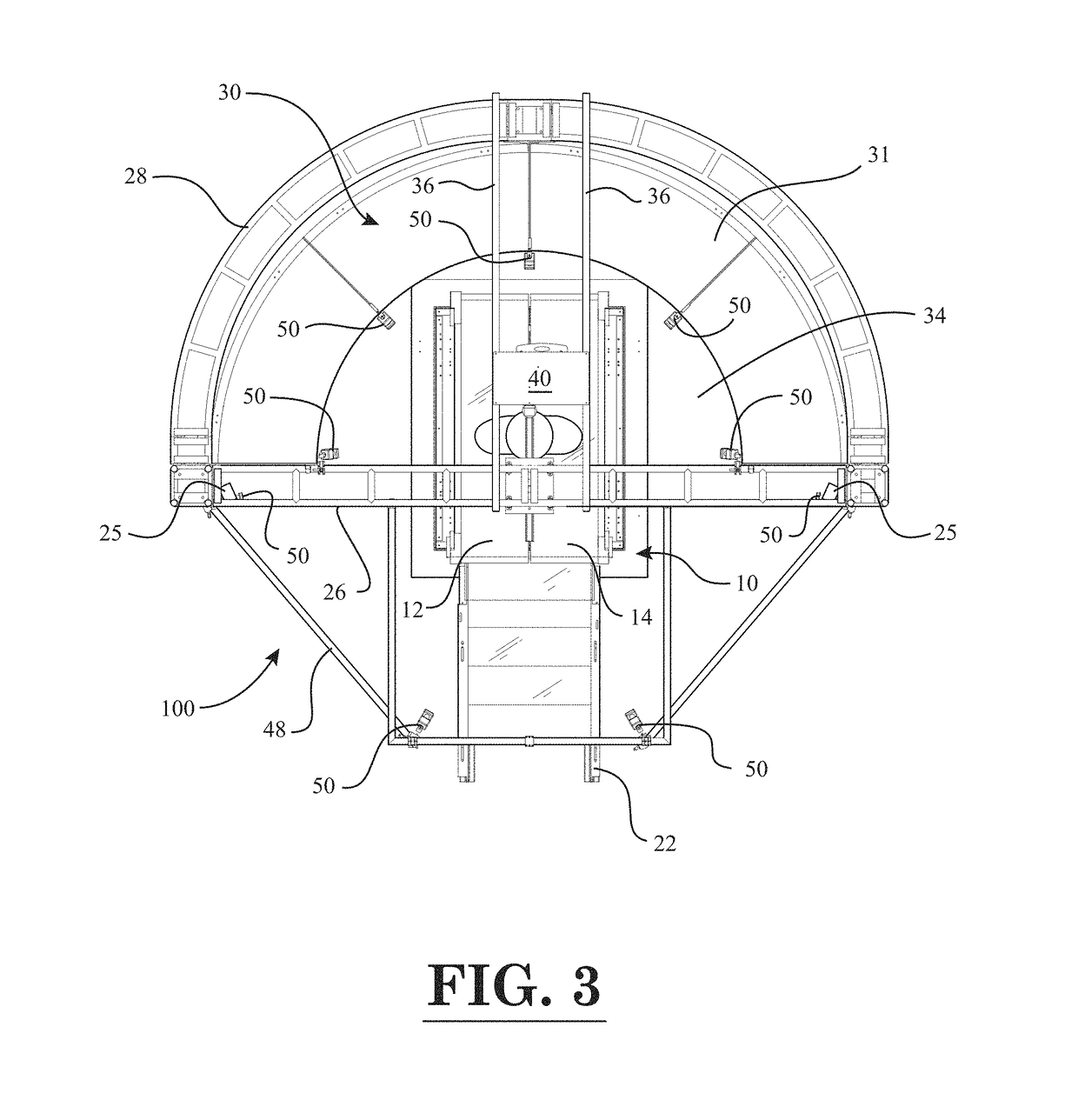
[0039]FIG. 3 is a top view of the force measurement system of FIG. 1;

[0040]FIG. 4 is a side view of the force measurement system of FIG. 1;

second embodiment

[0041]FIG. 5 is a perspective view of a force measurement system with a force measurement assembly in the form of an instrumented treadmill, according to the invention;

[0042]FIG. 6 is a front view of the force measurement system of FIG. 5;

[0043]FIG. 7 is a perspective view of a concave projection screen of the force measurement systems of FIGS. 1 and 5;

[0044]FIG. 8 is a longitudinal sectional view of the concave projection screen of FIG. 7;

[0045]FIG. 9 is a block diagram of constituent components of the force measurement system with a force measurement assembly in the form of an instrumented treadmill, according to an embodiment of the invention;

[0046]FIG. 10 is a block diagram of the software and hardware architecture of the force measurement system with the force measurement assembly in the form of the instrumented treadmill;

[0047]FIG. 11 is a screen image of an immersive grocery aisle scene displayed on the output screen of the visual display device of the force measurement syste...


PUM


Abstract

A force measurement system includes a force measurement assembly with a top surface configured to receive at least one portion of the body of a subject and at least one force transducer configured to sense forces and/or moments being applied to the top surface; at least one visual display device having an output screen configured to at least partially circumscribe three sides of a torso of the subject, and one or more data processing devices operatively coupled to the force measurement assembly and the at least one visual display device. In one or more embodiments, the force measurement assembly may be in the form of an instrumented treadmill. In one or more further embodiments, the force measurement system may additionally comprise a motion capture system configured to detect the motion of one or more body gestures of the subject.

Description

CROSS-REFERENCE TO RELATED APPLICATIONS[0001]This is a continuation-in-part of U.S. Nonprovisional patent application Ser. No. 15 / 242,558 entitled “Force Measurement System That Includes A Force Measurement Assembly, A Visual Display Device, And One Or More Data Processing Devices”, filed on Aug. 21, 2016, and further claims the benefit of U.S. Provisional Patent Application No. 62 / 208,671, entitled “Force Measurement System”, filed on Aug. 22, 2015, the disclosure of each of which is hereby incorporated by reference as if set forth in their entirety herein.STATEMENT REGARDING FEDERALLY SPONSORED RESEARCH OR DEVELOPMENT[0002]Not Applicable.NAMES OF THE PARTIES TO A JOINT RESEARCH AGREEMENT[0003]Not Applicable.INCORPORATION BY REFERENCE OF MATERIAL SUBMITTED ON A COMPACT DISK[0004]Not Applicable.BACKGROUND OF THE INVENTION1. Field of the Invention[0005]The invention generally relates to force measurement systems. More particularly, the invention relates to a force measurement system ...

Claims


Application Information

Patent Timeline
Patent Type & Authority Patents(United States)
IPC IPC(8): A61B5/103G06F3/01G06F3/14
CPCG06F3/011G06F3/1446G06F3/017G06F3/013A61B5/1036G06F3/012G06F2203/012A63F13/25A63F13/90A63F13/211A63F13/24A63F13/5255A63F13/218A63F13/212G01G19/50A61B5/6892A61B5/6895A61B5/1038A61B5/112G06F3/147G09G2340/12G09G2380/08A63B2024/0096A63B2071/0677A63B2071/0683A63B2024/0093A63B24/0087A63B2071/0638A63B2220/51A63B2220/52A63B2220/10A63B2220/30A63B2220/803A63B2220/807A63B2220/806A63B2220/20A63B22/0242A63B2071/0636A63B2024/0009A63B24/0003A63B71/0622A63B2071/0625A63B2071/0081A63B2220/80A63B2225/50A63B2209/02A63B2220/833A63B2024/009A63B2220/40A63B71/0619A63B2209/00
Inventor BERME, NECIPHOFFMAN, BENJAMIN ROBERTGHASSAB, SASANPITALE, JASWANDI TUSHAR
Owner BERTEC
Why Eureka
Try Eureka