Key and lock

a key and lock technology, applied in the field of keys and locks, can solve the problems of limited security of locks, difficult, and difficult to produce false keys, and achieve the effect of guarantying a high security level

Active Publication Date: 2018-03-20
URBANALPS
View PDF45 Cites 4 Cited by
  • Summary
  • Abstract
  • Description
  • Claims
  • Application Information

AI Technical Summary

Benefits of technology

[0054]For manufacturing the key an additive manufacturing process may be used. Additive manufacturing allows intricate features of great complexity to be produced, even in the internal areas. For example, selective laser melting (SLM) is used, in which the geometry of the key is built by the combination of powder material and laser power in a layer by layer basis. Other possible additive manufacturing processes make use of at least one of laser sintering, laser melting, electron beam melting, fused deposition modeling, material jetting, photopolymer jetting, binder jetting, stereolithography and injection. The additive manufacturing process allows the creation even of highly complex internal structures. Thus, it is possible to provide a set of multiple keys each having a unique coding, which cannot be duplicated by conventional methods and therefore guarantees a high security level.

Problems solved by technology

Such improvements have also made lock picking techniques, including impression methods of producing false keys, more difficult.
Despite improvements in the well-designed cylinder lock art, the security of these locks is still limited due to, among others, the following factors:Unauthorized duplications may be easily obtained by use of conventional machines that operate on the premise of the key having one or two axes;At present, keys have a simple design and structure whose external features may be easily interpreted by an expert and may also be reproduced by impression methods or even by use of simple cutting tools.
The limited number of keying combinations is due to a series of factors such as: a) the market demand for small and thin keys, which reduce the range of lock components; b) key production being based only on one or two dimensions: the axial positioning and the depth of the key bittings; c) the technical limitation of increasing the number of tumbler pins above a certain quantity, without increasing the cost and complexity of the lock.
Increasing the number of key bittings incrementally resulted in a higher number of unique keys, greatly reducing the possibility of a key operating a cylinder other than its own.
Notwithstanding the above mentioned technological progress in this field, the current market demands a more sophisticated and secure key and lock system, with a new concept of geometries and which does neither allow easy access to the security features nor permit its reproduction with conventional machines.

Method used


Image

  • Key and lock
  • Key and lock
  • Key and lock

Examples


Embodiment Construction

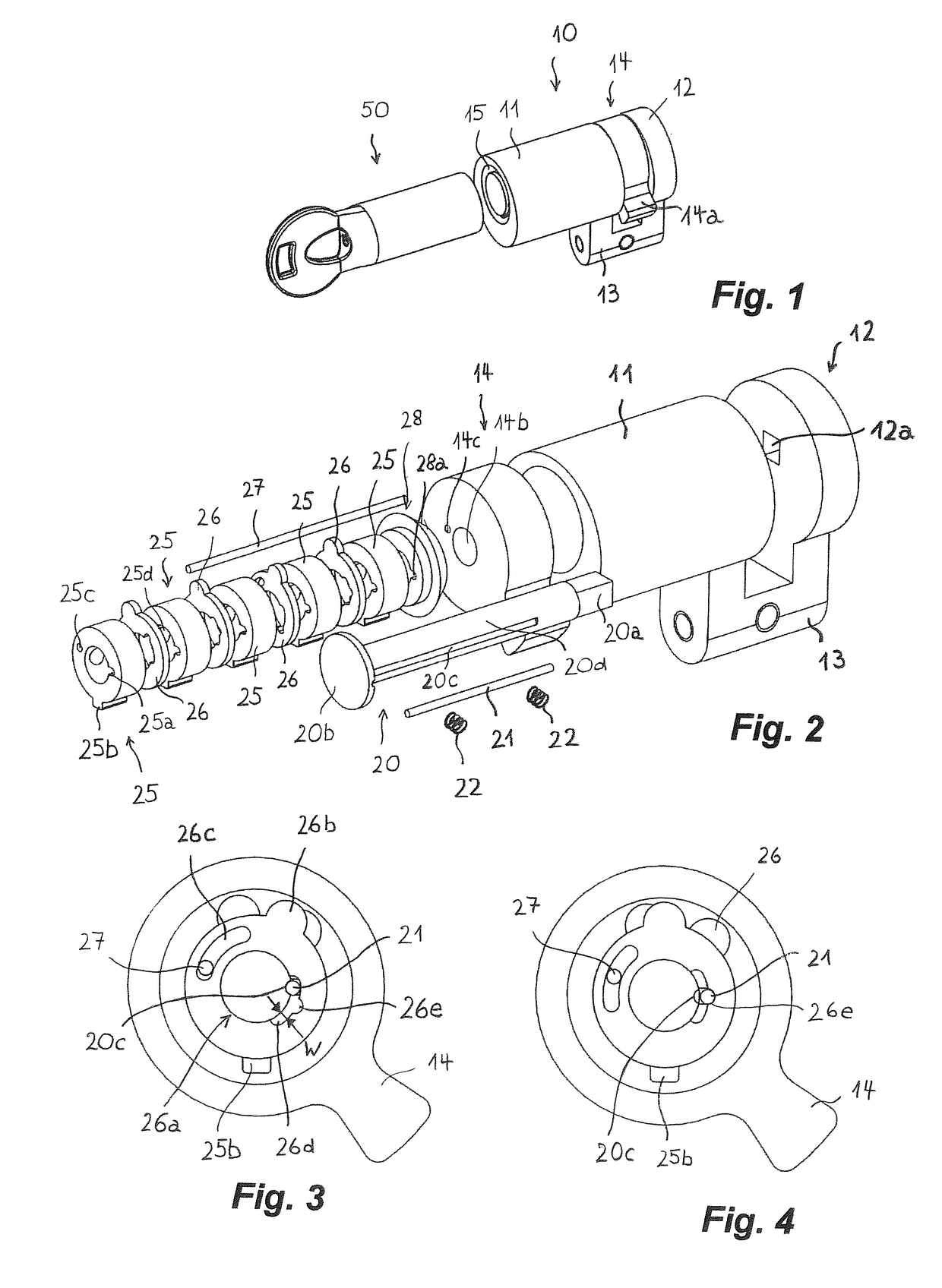
[0109]FIG. 1 shows a lock 10 together with a key 50. The lock 10 comprises a housing 11 enclosing the validating means for validating the key 50, an end plate 12 connected to the housing 11 via a bridge element 13 and a driving element 14 with a cam 14a, which is arranged between the spacing of the housing 11 and the end plate 12. If the correct key 50 is inserted, the driving element 14 can be rotated to unlock or lock the actual locking mechanism, e.g. a bolt of a door or the like.

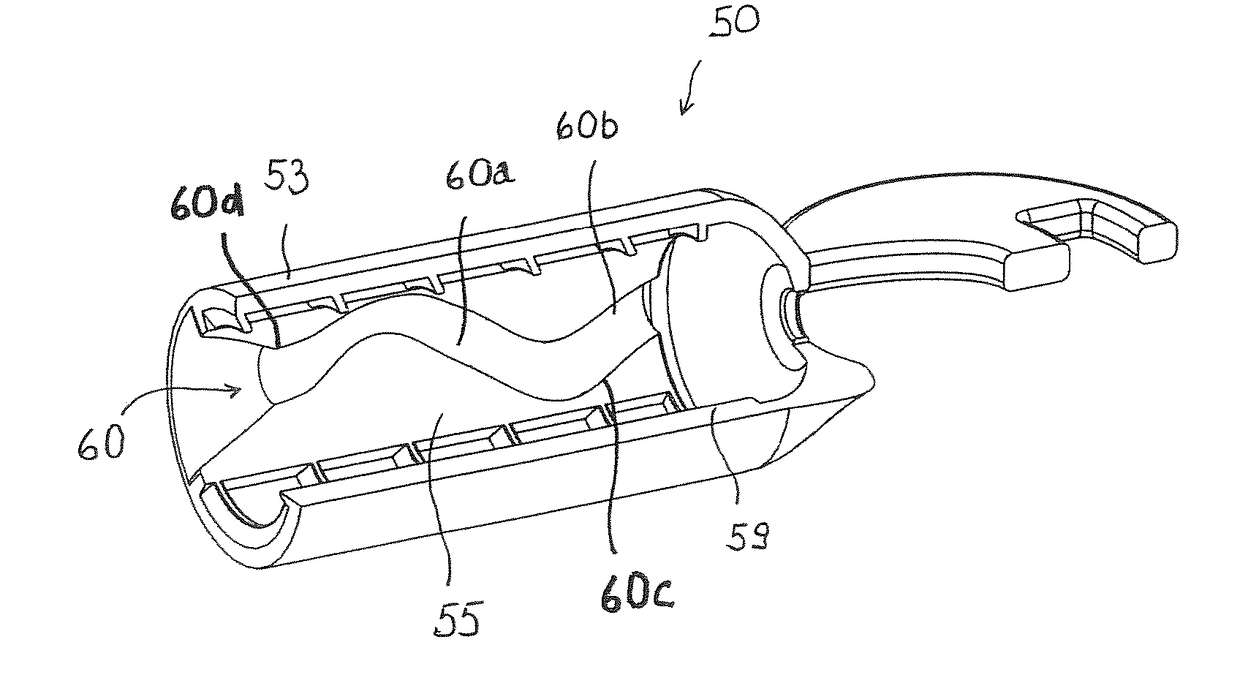
[0110]The lock 10 is designed such that a key 50 with a hollow geometry can be inserted. To this end, the lock 10 has a key cavity 15 which surrounds the validating means. The key cavity 15 has an annular form for receiving a portion of the key, in which a coding cavity is formed (see e.g. the coding cavity 55 in FIG. 11).

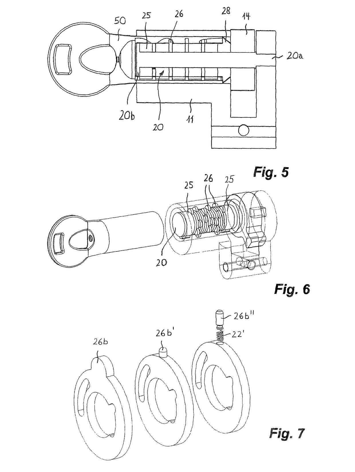
[0111]FIG. 2 shows the various components of the lock 10. The latter comprises a stator 20, which in the assembled state extends through the housing 11 and the driving element 14 into a...


PUM


Abstract

A key including at least one coding cavity (55) defining a hollow geometry for coding the key. The geometry includes at least one internal undercut (60a, 60b). The lock for validating a key comprises blocking means (21, 22) coupled to a driving part (14) and validating means (25, 26) which are coupled to the blocking means so as to change the state of the blocking means when the key used with the lock has a correct coding. The validating means (25, 26) protrude at least partially into the key cavity of the lock in order to introduce the validating means at least partially into the coding cavity (55) of the key and to sense the inner face of the coding cavity.

Description

CROSS REFERENCE TO RELATED APPLICATIONS[0001]The present application is a 35 U.S.C. § 371 National Phase conversion of PCT / CH2014 / 000146, filed Oct. 8, 2014, which claims the benefit of Swiss patent application no. 1740 / 13, filed Oct. 11, 2013 and Swiss patent application no. 631 / 14, filed Apr. 25, 2014, the disclosures of which are incorporated herein by reference. The PCT International Application was published in the English language.TECHNICAL FIELD OF THE INVENTION[0002]The present disclosure relates to a key and a lock.Background[0003]Many significant technical improvements in cylinder lock art have been introduced into the market in the last two or three decades. These have had the purpose, among others, of increasing the number of lock combinations and / or the complexity of key duplication.[0004]Typically, improvements in increasing the number of keying combinations have been obtained by:[0005]Increasing the number of tumbler pins and holes.[0006]Producing keys with very compl...

Claims


Application Information

Patent Timeline
Patent Type & Authority Patents(United States)
IPC IPC(8): E05B19/00E05B29/00E05B49/00E05B47/00
CPCE05B19/0023E05B19/0041E05B29/0013E05B49/006E05B19/0058E05B29/0066E05B47/0045E05B19/0047
Inventor OJEDA GONZALEZ-POSADA, ALEJANDROREINERT, FELIX MICHAEL
Owner URBANALPS
Why Eureka
Try Eureka