
Method and control device for circuit layout migration

a control device and circuit technology, applied in the field of methods and, can solve problems such as long runtimes and failure to find a solution at all

Active Publication Date: 2018-03-27
NXP USA INC
View PDF4 Cites 4 Cited by
  • Summary
  • Abstract
  • Description
  • Claims
  • Application Information

AI Technical Summary

Benefits of technology

The present invention provides a way to move the layout of a circuit from one place to another. This can be useful for designing and testing new circuit designs. The invention includes a method, software, and a control device for this process. This invention makes it easier to create and test new circuit designs, which can save time and money.

Problems solved by technology

Existing solutions for automatic layout migration employ procedures that tend to over-constrain the compaction problem, which may result in long runtimes or even the failure to find a solution at all.

Method used


Image

  • Method and control device for circuit layout migration
  • Method and control device for circuit layout migration
  • Method and control device for circuit layout migration

Examples


Embodiment Construction

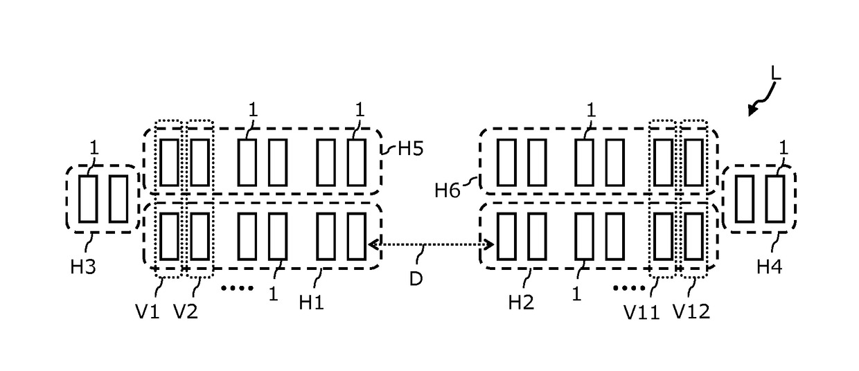
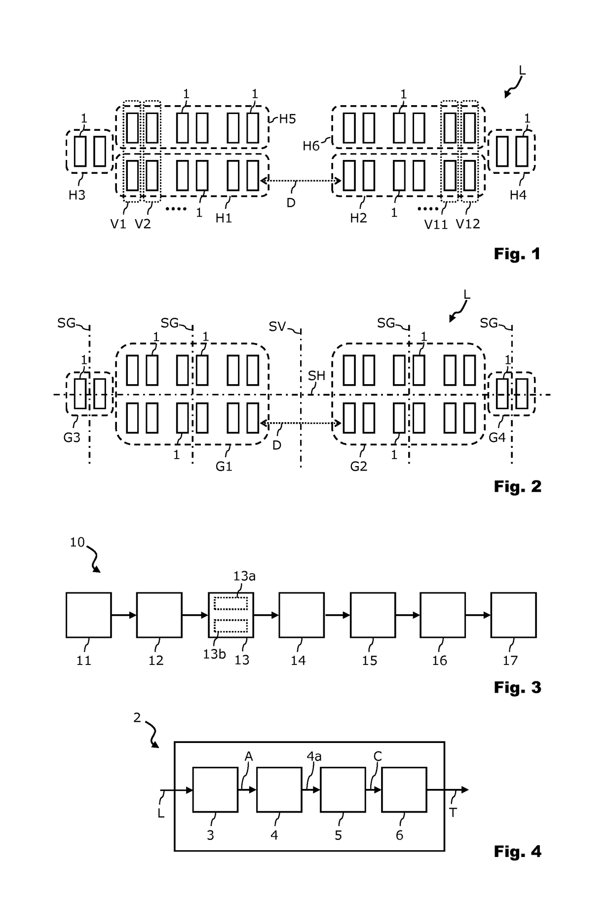
[0014]Referring first to FIG. 3, this schematically illustrates a method 10 for analog circuit layout migration, including but not limited to the exemplary analog circuit layouts as illustrated and explained in conjunction with FIGS. 1 and 2. The method 10 may be implemented by using a control device such as the control device 2 in FIG. 4. The method 10 may comprise, at 11, creating a list of layout components 1 in a source layout L. In this respect, it should be noted that the layout L is a set of data defining what structural features are to be present, as well as respective meta-information about the placement and orientation of the components 1 on an underlying fabrication substrate or die. However, for the sake of understanding, in the drawings the actual layout of the circuit, i.e. the physical circuit components 1 placed and oriented according to the layout L on an underlying fabrication integrated circuit substrate or die are shown. The layout components may for example comp...


PUM


Abstract

A method for circuit layout migration comprises creating a list of layout components in a source layout; determining a plurality of first groups of layout components being regularly aligned horizontally or vertically; determining first subsets of layout components which each belong to at least two of a respective set of determined first groups; determining a plurality of second groups of layout components, each second group comprising mutually exclusive ones of the first subsets of layout components; determining symmetry axes for pairs of second groups; building a constraint graph of the layout components of the source layout using alignment constraints for the alignment of layout components within each of the second groups and distance constraints for preserving a regularity pattern within each of the second groups and symmetry constraints for the determined symmetry axes for pairs of second groups; and performing constraint-graph-based compaction of the source layout.

Description

CROSS REFERENCE TO RELATED APPLICATION(S)[0001]The present application claims priority to Russian Patent Application No. RU 2014122499, entitled “METHOD AND CONTROL DEVICE FOR CIRCUIT LAYOUT MIGRATION,” filed on Jun. 4, 2014, the entirety of which is herein incorporated by reference.FIELD OF THE INVENTION[0002]This invention relates to a method, a computer readable program product and a control device for circuit layout migration, in particular in analog circuit layout migration on the basis of constraint graphs.BACKGROUND OF THE INVENTION[0003]Layouts for analog circuitry usually satisfy certain geometrical and topological layout constraints that enable the circuitry to function correctly and to comply with design specifications. Such geometrical and topological layout constraints include for example symmetries between components, absolute placement positions, relative placement positions, relative orientations of one type of components with regard to another type of components and...

Claims


Application Information

Patent Timeline
Patent Type & Authority Patents(United States)
IPC IPC(8): G06F9/455G06F17/50
CPCG06F17/5063G06F17/5072G06F30/36G06F30/392G06F2111/04
Inventor ROZENFELD, VLADIMIR PAVLOVICHMAZIASZ, ROBERT L.SOTNIKOV, MIKHAIL ANATOLIEVICH
Owner NXP USA INC
Learn More