Injection moulding device

a technology of injection molding and molds, which is applied in the field of injection molding devices, can solve the problems of complex design of devices known from the prior art, and counteract economic efficiency in particular during maintenance works, and achieve the effect of considerably simplifying the design of the central mold hal

Inactive Publication Date: 2018-04-03
FOBOHA GERMANY
View PDF13 Cites 1 Cited by
  • Summary
  • Abstract
  • Description
  • Claims
  • Application Information

AI Technical Summary

Benefits of technology

[0015]It is an object of the invention to provide an injection molding device of the kind mentioned at the beginning, which allows a particularly simple and space-saving design and allows the number of cavities to be maximized.
[0019]The first and third mold halves have first and second cavity halves, which interact in the region of a first parting plane in order to form first cavities in the closing position of the injection molding device. The second and third mold halves have third and fourth mold halves that interact in the region of a second parting plane in order to form second cavities in the closing position of the injection molding device. As a rule, a plurality of cavities exists for each parting plane for enhancing efficiency. The cavity halves are as a rule designed in multiple pieces. As a rule, for each cavity at least one region of one part forming the cavity is movably arranged on a transfer system. These carriers are serve for transporting parts produced in the first parting plane into cavities of the second parting plane.
[0023]The rod may again be designed to be hollow and may be used for transferring media of the kind mentioned at the beginning. One advantage consists in the fact that only a minimum of non-rotatable parts is necessary and the design of the central mold half can be considerably simplified compared to the prior art.

Problems solved by technology

The devices known from the prior art often have problems in connection with carrying media (air, water, hydraulic oil, data) from and to the central mold half and with regard to the flexibility of the rotary system.
Further, the devices known from the prior art have a complex design that counteracts economic efficiency in particular during maintenance works.

Method used


Image

  • Injection moulding device
  • Injection moulding device
  • Injection moulding device

Examples


Embodiment Construction

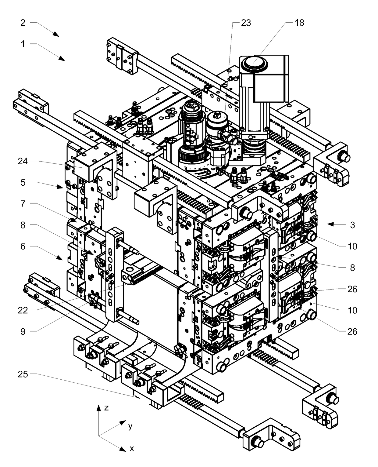
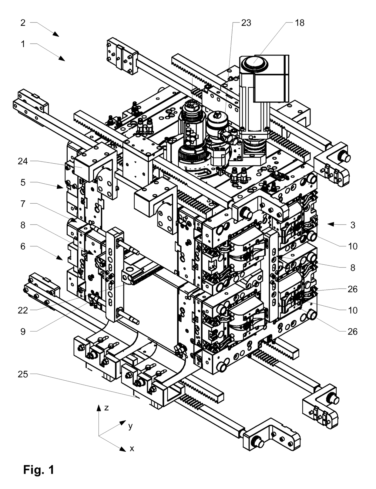
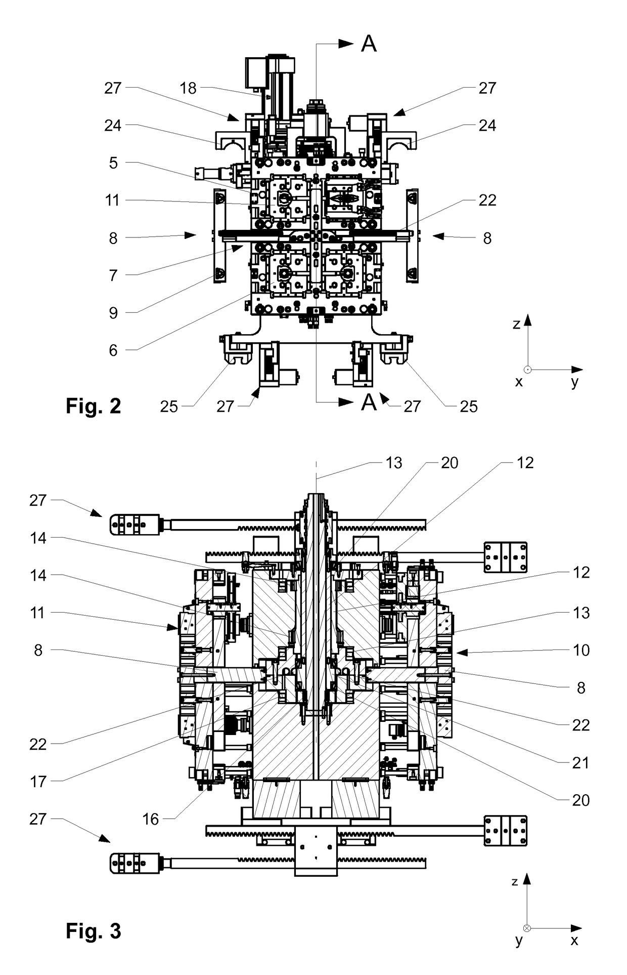
[0030]What is not shown are the first and second mold halves, which are also part of the injection molding device and are arranged, with reference to the x-direction (first direction), on opposite sides of the third mold half and are designed to be adjustable relative thereto in the first direction. The two mold halves (first and 10 second) that are arranged on the outside have a conventional construction and will therefore not be explained in detail. They interact with a first lateral surface 3 in the region of a first parting plane and with a second lateral surface 4 of the third mold half 1 in the region of a second parting plane.

[0031]The injection molding device 2 is provided for an operative connection with a commercially available injection molding machine. In this context, the first and second mold halves are fastened to the tool platens of the injection molding machine. The central third mold half is mounted on the machine bed and / or the tie bars of the injection molding ma...


PUM

PropertyMeasurementUnit
mechanicalaaaaaaaaaa
flexibilityaaaaaaaaaa
mechanical forcesaaaaaaaaaa

Abstract

An injection molding device includes a first mold half and a second mold half, which is arranged so that the second mold half can be moved linearly in in relation to the first mold half. A third mold half, arranged between the first and the second mold halves, interacts with the first mold half in a first parting plane to form first cavities and interacts with the second mold half in a second parting plane to form second cavities. The third mold half includes an upper part and a lower part, spaced apart by a slot. A first drive shaft is arranged in an interior of the third mold half. The first drive shaft includes at least one carrier arranged on an arm so that the carrier is movable in a radial direction. The first drive shaft is supported with respect to both the upper part and the lower part by at least one bearing.

Description

BACKGROUND OF THE INVENTION[0001]Field of the Invention[0002]The present invention relates to the area of injection molding devices, in particular injection molding devices for the injection molding of plastics.[0003]Discussion of Related Art[0004]From the prior art, injection molding devices are known which have a first mold half and a second mold half that can be linearly displaced in relation to the first mold half. Between the first and second mold halves, a third central mold half (central part) is attached, which is also disposed so as to be linearly displaceable in the same direction in relation to the first and second mold halves. A coordination mechanism ensures that the third, central mold half, during the opening and closing of the injection molding device, is positioned centrally between the first and second mold halves and is moved in a manner coordinated with these.[0005]The first and third mold halves interact in the region of a first parting plane and the second and ...

Claims


Application Information

Patent Timeline
Patent Type & Authority Patents(United States)
IPC IPC(8): B29C45/16B29C45/26
CPCB29C45/162B29C45/2606B29C2045/1617
Inventor ARMBRUSTER, RAINER
Owner FOBOHA GERMANY
Why Eureka
Try Eureka