Converter circuit with two converter elements

a converter circuit and converter element technology, applied in the field of power electronics, can solve the problems of large amplitude components that are highly undesirable, require a correspondingly large amount of space, and are very expensive, and achieve the effects of low load, significant increase in the overall availability of the converter circuit, and low cos

Inactive Publication Date: 2007-05-31
ABB (SCHWEIZ) AG
View PDF10 Cites 4 Cited by
  • Summary
  • Abstract
  • Description
  • Claims
  • Application Information

AI Technical Summary

Benefits of technology

[0006] The converter circuit according to the invention has a first and a second converter element, with each converter element having a DC voltage circuit and in each case one converter element phase of the first converter element being connected to a respective converter element phase of the second converter element. Furthermore, the converter circuit according to the invention has a transformer, with the secondary windings of the transformer being connected to the connected converter element phases of the first and second converter elements. Furthermore, one secondary winding in each case is connected in series in each connection of one converter element phase of the first converter element to one converter element phase of the second converter element. According to the invention, each secondary winding is formed by two winding elements connected in series with one another, with the junction point of the two winding elements forming a neutral-point connection. Furthermore, two filter capacitors which are connected in series with one another are in each case connected in parallel with each secondary winding. This respective connection of a secondary winding which is formed by the winding elements advantageously results in a major reduction in amplitude components relating to the switching frequency of the converter circuit during its operation in output currents and in output voltages of the converter circuit, so that these amplitude components virtually do not occur in comparison to conventional converter circuits. Furthermore, amplitude components relating to odd-numbered multiples of the switching frequency can advantageously be likewise greatly reduced by the respective connection of the secondary winding, so that these amplitude components are also very largely suppressed. An electrical supply network which is normally connected to the converter circuit via the transformer is thus advantageously not significantly or only extremely lowly loaded by amplitude components relating to the switching frequency and its odd-numbered multiples. Furthermore, one of the winding elements of one secondary winding together with one of the associated filter capacitors in each case forms a resonant circuit, which is advantageously used to further reduce the amplitude components relating to the switching frequency and its odd-numbered multiples in output currents and in output voltages of the converter circuit. This allows the. overall availability of the converter circuit to be significantly increased.

Problems solved by technology

These large amplitude components are very highly undesirable, for example, when the converter circuit is connected by means of a transformer to an electrical supply network.
However, in order to achieve a certain advantageous reduction in the amplitude component relating to the switching frequency in the output currents and in the output voltages, filter capacitors such as these and the inductances must be designed to have large capacitance and inductance values, respectively, and thus have a large physical size and are heavy, thus requiring a correspondingly large amount of space so that they are thus, overall, very expensive.
In addition, the design of the converter circuit and the relevant maintenance of the converter circuit are made more complicated by such large inductances and filter capacitors, thus incurring additional costs.

Method used


Image

  • Converter circuit with two converter elements
  • Converter circuit with two converter elements
  • Converter circuit with two converter elements

Examples


first embodiment

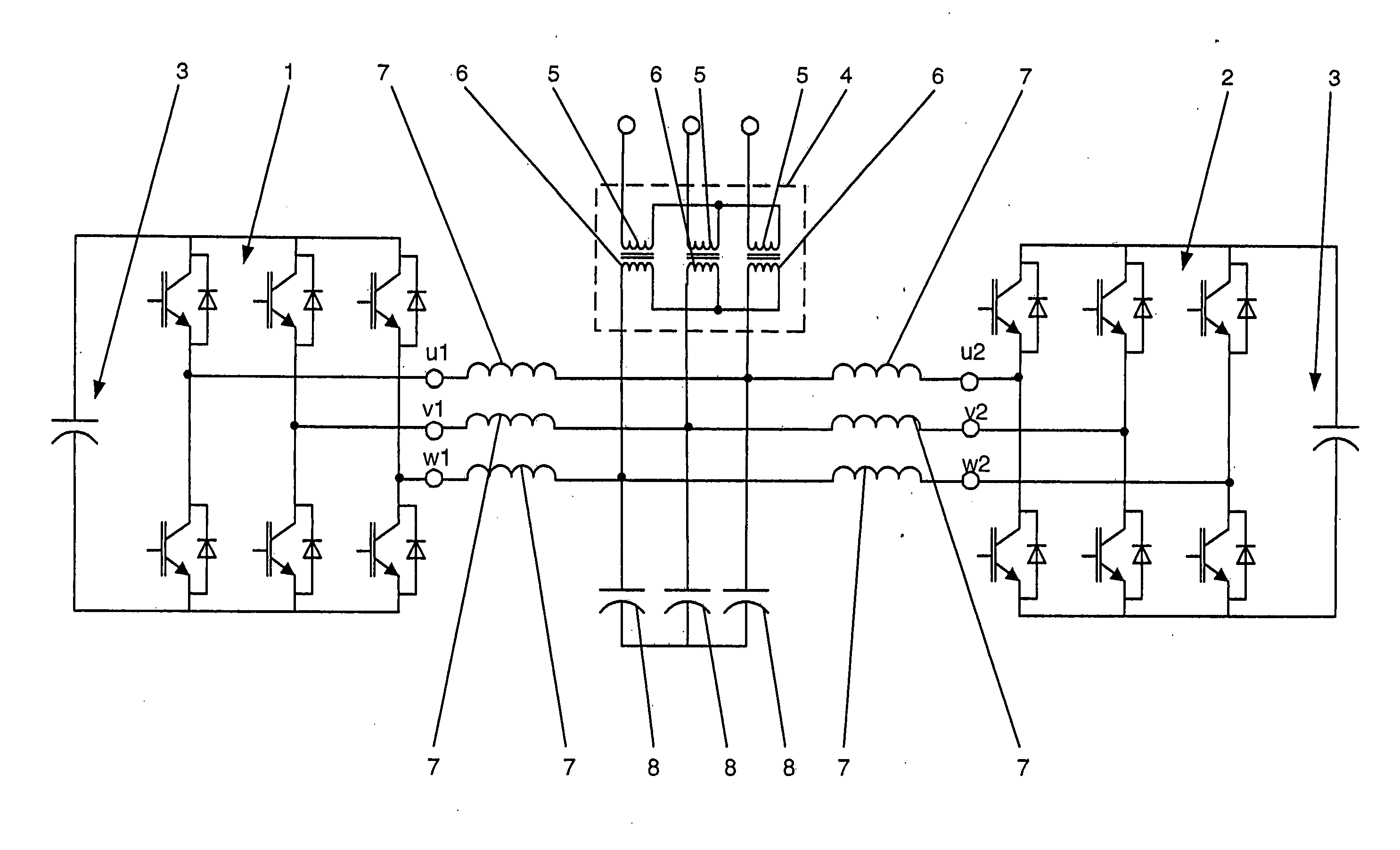
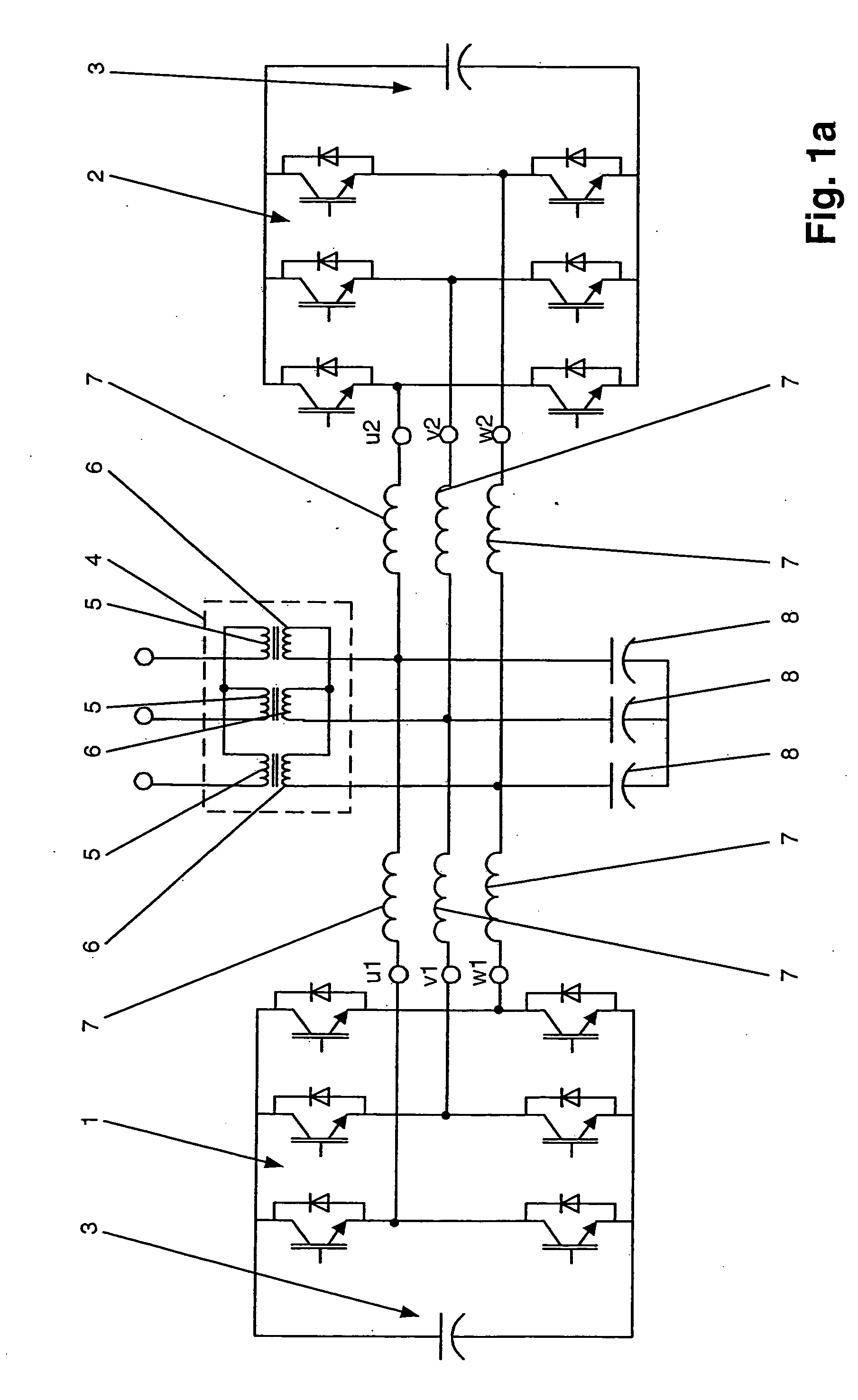
[0017]FIG. 2a shows a converter circuit according to the invention,

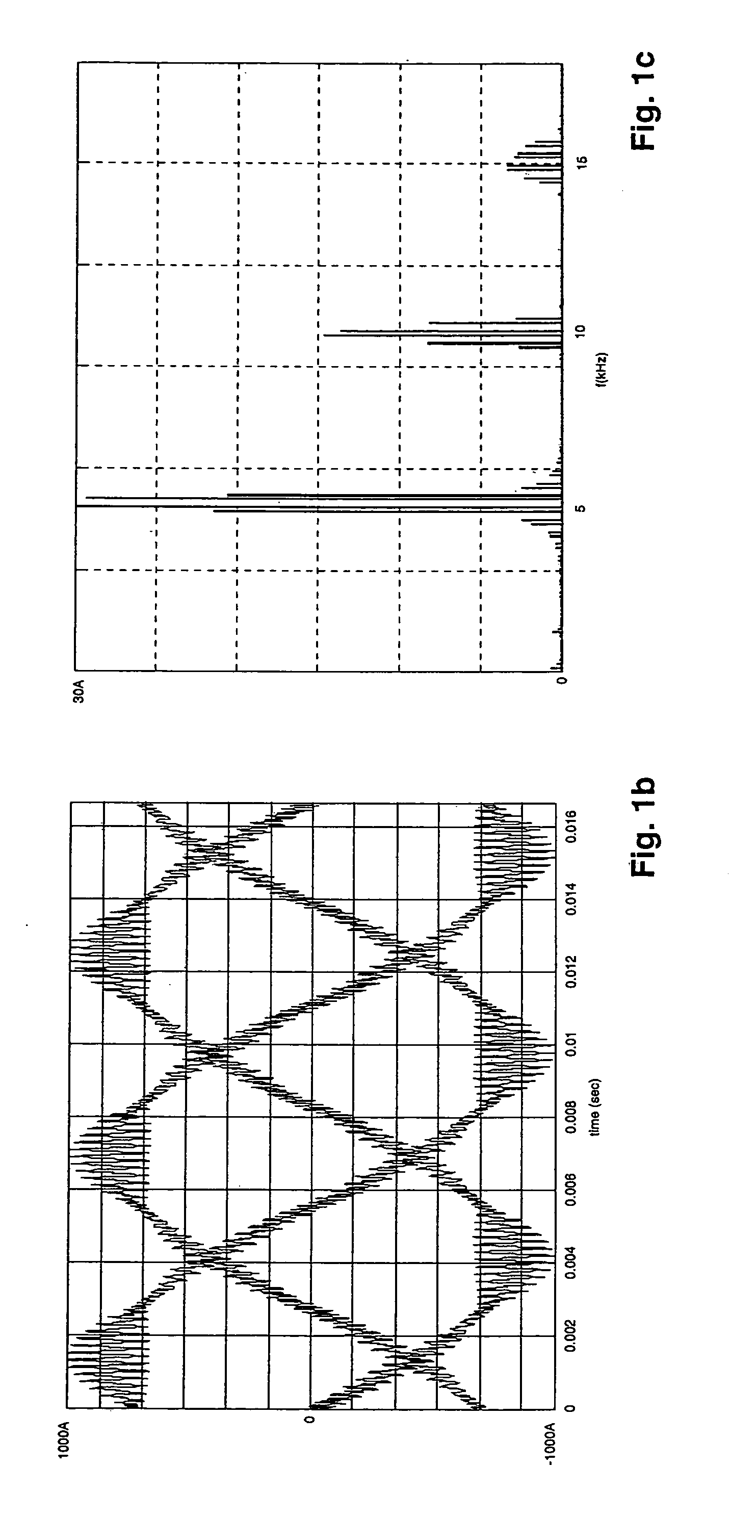
[0018]FIG. 2b shows a time profile of the output currents of the converter circuit as shown in FIG. 2a on the primary side of the transformer,

[0019]FIG. 2c shows a frequency spectrum of an output current as shown in FIG. 2b,

[0020]FIG. 2d shows a time profile of the output voltages of the converter circuit as shown in FIG. 2a on the primary side of the transformer,

[0021]FIG. 2e shows a frequency spectrum of an output voltage as shown in FIG. 2d,

second embodiment

[0022]FIG. 3 shows the converter circuit according to the invention,

third embodiment

[0023]FIG. 4 shows the converter circuit according to the invention,

[0024]FIG. 5 shows one embodiment of an energy storage device according to the invention,

[0025]FIG. 6 shows one embodiment of a drive system according to the invention, and

[0026]FIG. 7 shows one embodiment of a converter system according to the invention.

[0027] The reference symbols used in the drawing and their meanings are listed in summarized form in the list of reference symbols. In principle, identical parts are provided with the same reference symbols in the figures. The described embodiments represent examples of the subject matter of the invention, and have no restrictive effect.

Approaches to Implementation of the Invention

[0028]FIG. 2a shows a first embodiment of a converter circuit according to the invention. The converter circuit comprises a first and a second converter element 1, 2, with each converter element 1, 2 having a DC voltage circuit 3. As shown in FIG. 2a, each converter element 1, 2 is de...


PUM


Abstract

A converter circuit having a first and a second converter element is specified, with each converter element having a DC voltage circuit and in each case one converter element phase (u1, v1, w1) of the first converter element being connected to a respective converter element phase (u2, v2, w2) of the second converter element. Furthermore, a transformer is provided, with the secondary windings of the transformer being connected to the connected converter element phases (u1, v1, w1, u2, v2, w2) of the first and second converter elements. In order to ensure that virtually no amplitude components relating to the switching frequency of the converter circuit occur during its operation in the output currents of the converter circuit and in the output voltages of the converter circuit, one secondary winding is in each case connected in series in each connection of one converter element phase (u1, v1, w1) of the first converter element to one converter element phase (u2, v2, w2) of the second converter element, in which case each secondary winding is formed by two winding elements connected in series with one another, with the junction point of the two winding elements forming a neutral-point connection, and two filter capacitors which are connected in series with one another are in each case connected in parallel with each secondary winding.

Description

TECHNICAL FIELD [0001] The invention relates to the field of power electronics, and in particular to a converter circuit as claimed in the precharacterizing clause of the independent claim. PRIOR ART [0002] High-power voltage converter circuits are used in many applications nowadays. A converter circuit such as this has two converter elements, for example, for this purpose, with each converter element having a DC voltage circuit which is formed by a capacitor. Furthermore, each converter element has power semiconductor switches which are normally connected in such a manner that two switching voltage levels, specifically the positive intermediate circuit voltage and the negative intermediate circuit voltage, can be connected to the converter element phases of the associated converter element. Each converter element normally has three converter element phases, with one converter element phase of the first converter element in each case being connected to in each case one converter ele...

Claims


Application Information

Patent Timeline
Patent Type & Authority Applications(United States)
IPC IPC(8): H02M3/335H02J3/01H02J3/38H02M1/12H02M5/458H02M7/08H02M7/17H02M7/48H02M7/49
CPCH02M5/4585H02M7/49
Inventor PONNALURI, SRINIVASSTEINKE, JURGENSTEIMER, PETER
Owner ABB (SCHWEIZ) AG
Why Eureka
Try Eureka