Spiral ring full road interchange system

a full-circle interchange and spiral ring technology, applied in roadways, roads, construction, etc., can solve the problems of junctions presenting further transportation failures, drop in traffic effectiveness, and inability to answer transportation regulations for interchanges

Active Publication Date: 2018-04-03
MEROZ GILEAD +1
View PDF64 Cites 3 Cited by
  • Summary
  • Abstract
  • Description
  • Claims
  • Application Information

AI Technical Summary

Problems solved by technology

Junction may have limitations and drawbacks in three major aspects:Area—requirement to use very large areas for building a full road interchange, mainly due to trapped spaces.
Further, answering transportation regulations may not be feasible for interchanges having total area below 147,000 cubic meters (about 15 hectares).
This issue is of particular importance in dense and highly populated areas.Traffic—road design may particularly influence transportation capacity and driving speed and various other aspects of traffic flow, such as weaving (lane crossing) issues; sudden slowing down due to sharp curves and traffic ‘bottlenecks’; drop of traffic effectiveness when adding lanes in the same direction; problematic correction of navigation errors (such as performing an about-turn); and navigational complexities for the road user.Cost—high cost may be associated with building of transportation-efficient interchanges (transition speed and traffic capacity); and, possibly further impact based upon the land value.
It is noted that Buteliauskas's road junction presents a further transportation failure: when traveling within the interchange, the main traffic flow, mostly directed forward, forks to the right for a right turn, and forks to the left, for a left turn, which is out of keeping with accepted norms for an RTH driving system.
Further, Buteliauskas road junction offers limited flexibility by disallowing “direct” turns through the interchange central area making the traffic flow more complicated from the road user perspective.
Additionally, the Buteliauskas road junction does not answer various drawbacks such as high building cost high due to the construction are large requirements, road user possible confusion in a complex road system and provides no flexibility for better adaptation to the ground surface.

Method used


Image

  • Spiral ring full road interchange system
  • Spiral ring full road interchange system
  • Spiral ring full road interchange system

Examples


embodiment 400

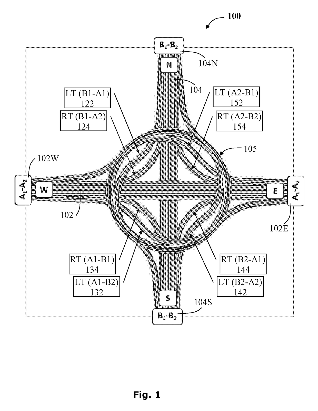
[0088]The structural embodiment 400 of the four-way spiral road junction includes a highway spoke 102W having an inbound section A1 and an outbound section A2; a highway spoke 102E having an inbound section A2 and an outbound section A1; a highway spoke 104N having an inbound section B1 and an outbound section B2 and highway spoke 104S having an inbound section B2 and an outbound section B1; a flyover intersection crosspass 410; a cross-over connecting road associated with each highway spoke, as described hereinafter; and a ring-road interchange 415 comprising four crosspasses providing a continuous path for each highway spoke, as exemplified by the continuous path 420 allowing a left turn, as described hereinafter.

[0089]The spiral road junction 400 further includes a ring-road interchange 415 comprising a plurality of spoke-traversing crosspasses where each crosspass traverses a highway spoke.

[0090]The cross-over connecting road, providing a left turn 442 (B1-A1), is exemplified by...

embodiment 900

[0142]Reference is now made to FIG. 9, showing a schematic top-view embodiment 900 of a six-way road junction of an “outward spiral interchange” type for an RHT driving system, exemplifying un-interrupted traffic access to all possible directions from a specific highway spoke.

[0143]The schematic top-view embodiment 900 of the six-way spiral road junction includes a north highway spoke 802N having an inbound section B1 and an outbound section B2; a south highway spoke 802S having an inbound section B2 and an outbound section B1; a north-east highway spoke 806NE having an inbound section C1 and an outbound section C2; a south west highway spoke 806SW having an inbound section C2 and an outbound section C1; a south east highway spoke 804SE having an inbound section A1 and an outbound section A2 and an highway spoke 804NW having an inbound section C2 and an outbound section C1.

[0144]The six-way spiral road junction, as shown in the schematic top-view embodiment 900 provides access from ...

embodiment 1700

[0199]The three-way “T” shaped road junction embodiment 1700, further includes a spoke-traversing crosspass 1732 associated with highway spoke 1202, a spoke-traversing crosspass 1734 associated with highway spoke 1204, a spoke-traversing crosspass 1736 associated with highway spoke 1736.

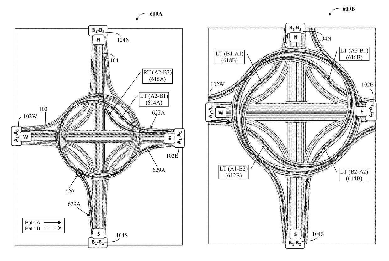
[0200]The right turn 1707, as indicated by the arrowed path A, provides the traffic with the possibility of performing a right turn leaving the inbound section C1 of the third highway spoke 1206 via a slip road 1722 through the spiral ring-road interchange 1726 to join the outbound section A2 of the second highway spoke 1202 via the slip road 1729. The correction region 420 provides a possible correction and disrupting the continuous path, to allow an about-turn 1708, as indicated by the dashed arrowed path B, provides the traffic with the possibility of performing an about-turn to return along the inbound section C1 of the third highway spoke 1706 to the outbound section of C2 via the slip road 1729...


PUM


Abstract

A spiral road junction system for connecting a plurality of highway spokes via a spiral road junction comprising adjacent-spoke connecting roads associated with each highway spoke, and a ring-road interchange traversing all the highway spokes. The ring-road interchange provides a continuous path from a slip road diverging from an entry highway spoke to an access road merging with an exit highway spoke.

Description

CROSS-REFERENCE TO RELATED APPLICATIONS[0001]This application is a U.S. National Phase Application under 35 U.S.C. 371 of International Application No. PCT / IB2014 / 063589, which has an international filing date of Jul. 31, 2014, and which claims priority and benefit from U.S. Provisional Patent Application No. 61 / 861,491, filed Aug. 2, 2013, the contents and disclosure of which are incorporated herein by reference in their entirety.FIELD OF THE INVENTION[0002]The present disclosure is directed to providing a spiral ring full interchange system. More specifically, the present disclosure relates to a system for connecting multiple highway spokes to each other via direct segments or direct crosspass road segments using a ring-road interchange.BACKGROUND OF THE INVENTION[0003]The exceptional urbanization, population growth, technological advancements recognized in all aspects of life in the 21st century present new challenges associated with the fast pace of modern life, in general with ...

Claims


Application Information

Patent Timeline
Patent Type & Authority Patents(United States)
IPC IPC(8): E01C1/04E01C1/00
CPCE01C1/002E01C1/04
Inventor MEROZ, GILEADTOREN, YARON
Owner MEROZ GILEAD
Why Eureka
Try Eureka