Road facility capable of enabling vehicles on crossing road of city not to intersecting

A technology of road facilities and cross roads, applied in the directions of roads, roads, buildings, etc., to solve the traffic congestion, wide application range, and shorten the driving time.

Inactive Publication Date: 2013-04-10
徐晓广
View PDF0 Cites 2 Cited by
  • Summary
  • Abstract
  • Description
  • Claims
  • Application Information

AI Technical Summary

Problems solved by technology

Practice has proved that it can only alleviate traffic congestion, b

Method used


Image

  • Road facility capable of enabling vehicles on crossing road of city not to intersecting
  • Road facility capable of enabling vehicles on crossing road of city not to intersecting
  • Road facility capable of enabling vehicles on crossing road of city not to intersecting

Examples


Embodiment 1

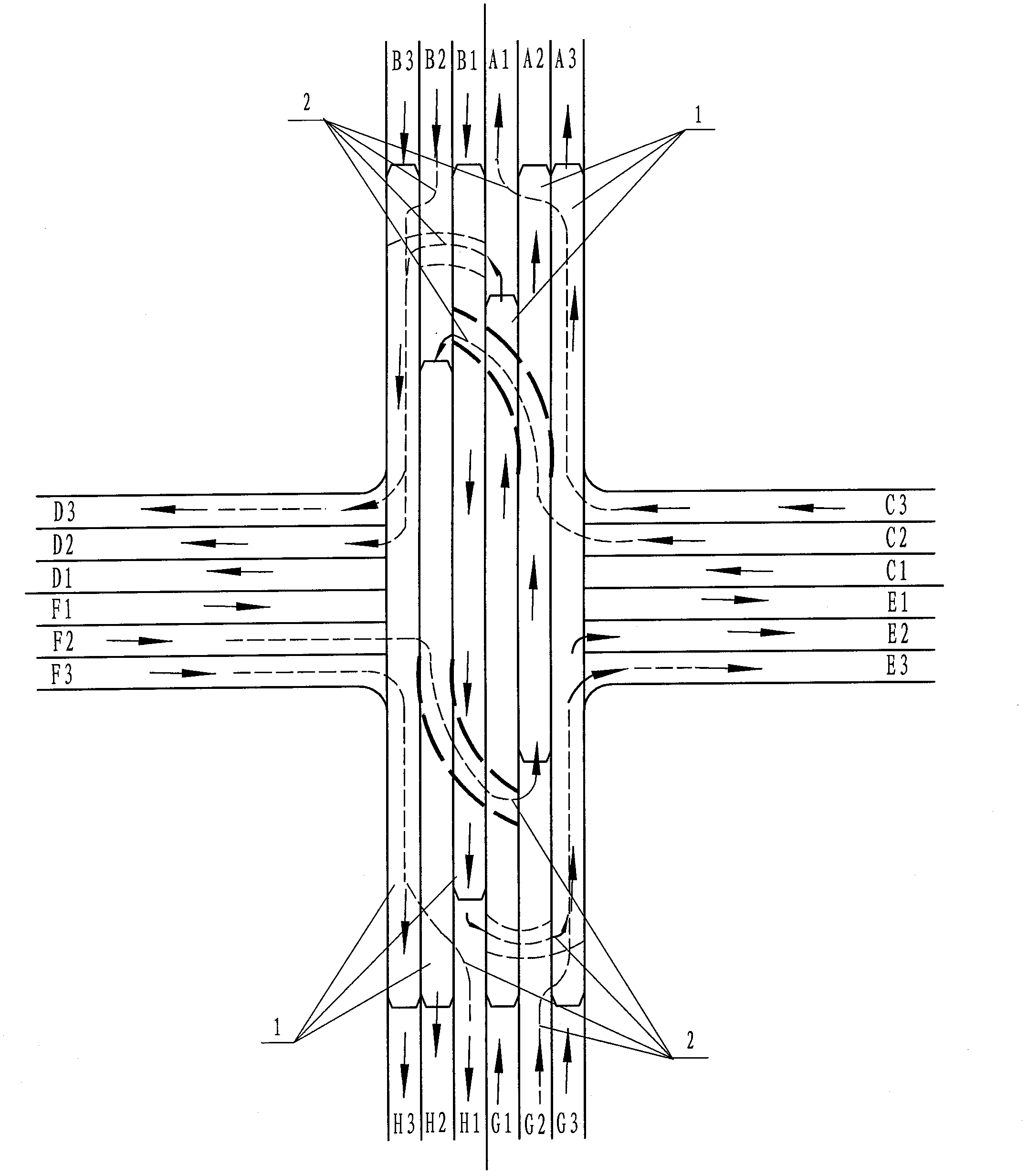
[0038] Depend on figure 1 , figure 2 It can be seen that in this embodiment: on both longitudinal sides of the crossing road, six lanes running in opposite directions in the longitudinal direction are respectively connected. On both lateral sides of the intersection, connect the six lanes traveling in opposite directions. On the lane along the longitudinal road on the intersection road, a corresponding driving bridge 1 is provided, and a corresponding connecting road 2 is arranged below the corresponding driving bridge 1 .

[0039] On the right side of the lane centerline on the south side of the longitudinal intersection road: there are G1, G2, and G3 lanes. On the intersecting road connected by the G1 and G2 lanes, the corresponding driving bridge 1 for turning across the intersecting road is provided in sequence. On the intersecting road connected by the G3 lane, there are straight corresponding driving bridges 1 crossing the intersecting road, and they are respectively...

Embodiment 2

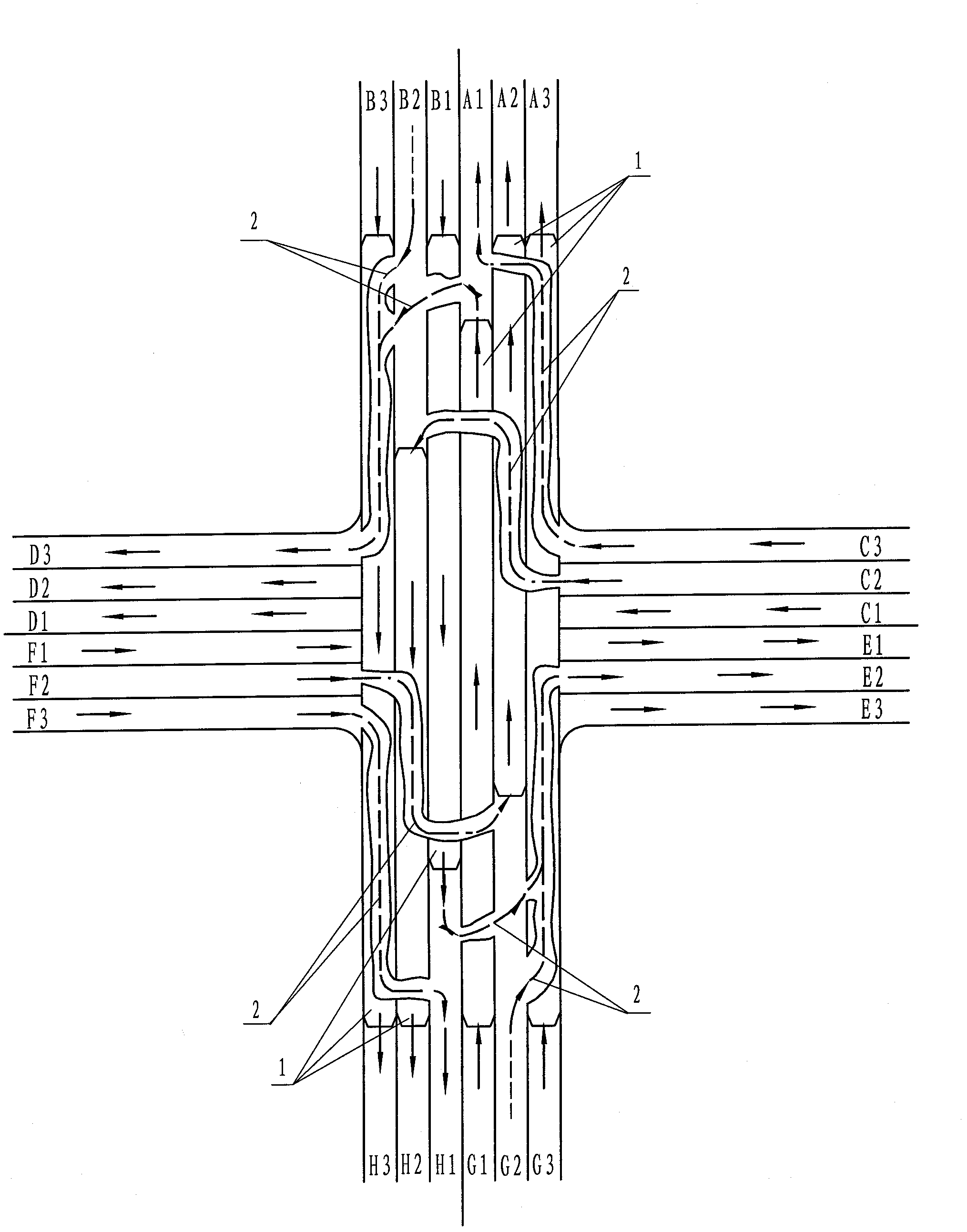
[0073] Depend on image 3 , Figure 4 It can be seen that in this embodiment: on both longitudinal sides of the crossing road, six lanes running in opposite directions in the longitudinal direction are respectively connected. On both lateral sides of the intersection, connect the six lanes traveling in opposite directions. On the lane along the longitudinal road on the intersection road, a corresponding driving bridge 1 is provided, and a corresponding connecting road 2 is arranged below the corresponding driving bridge 1 . An auxiliary lane 3 is provided outside the lanes on both sides of the longitudinal road.

[0074] On the right side of the lane centerline facing the south side of the longitudinal intersection: There are longitudinal G1, G2, and G3 lanes. On the right side of the G3 lane, there is an auxiliary lane 3. On the intersecting roads connected by the G1 and G2 lanes, corresponding driving bridges 1 for turning are provided in sequence. On the intersecting r...

Embodiment 3

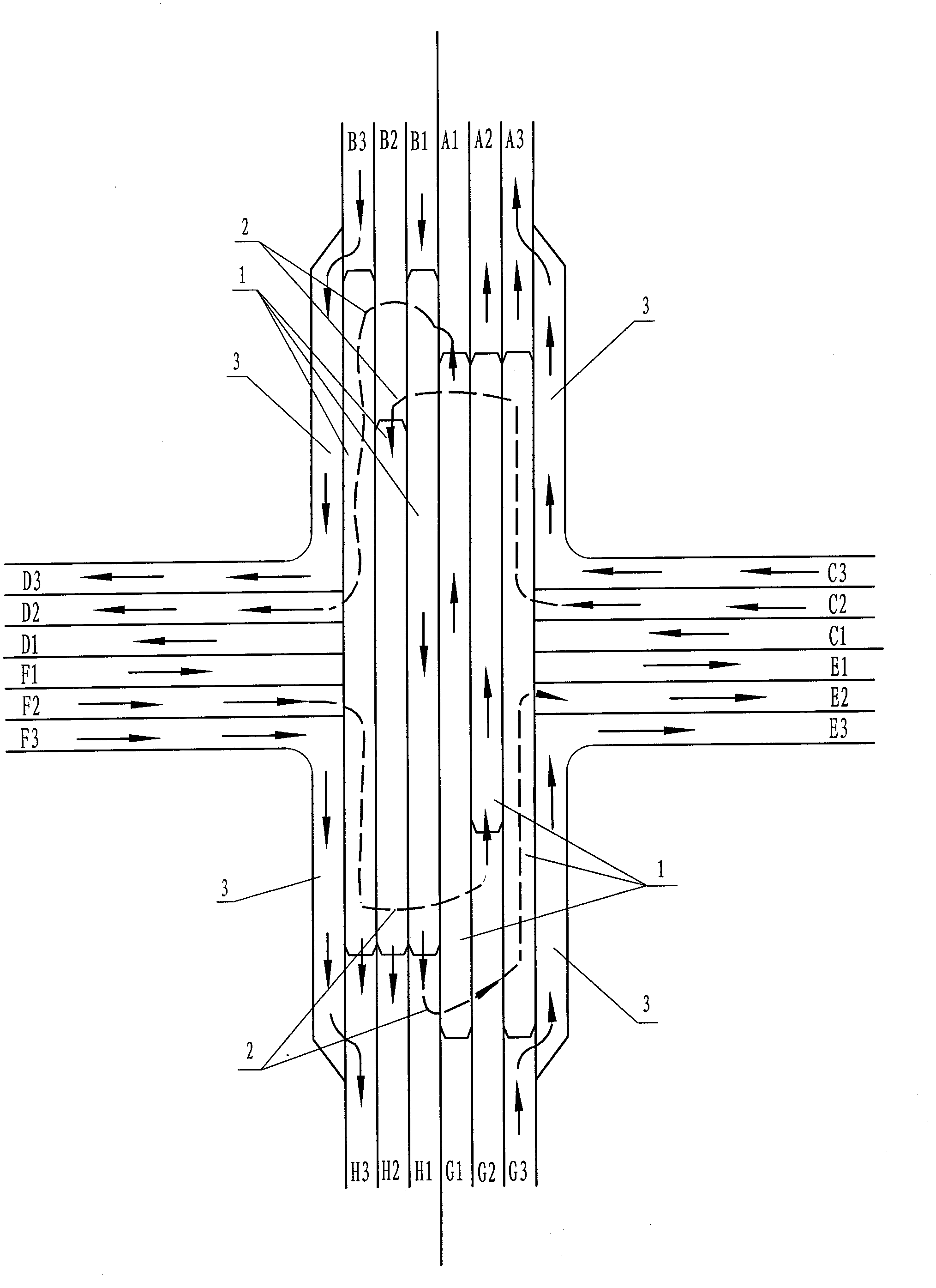
[0109] Depend on Figure 5 , Image 6 It can be seen that in this embodiment: on both longitudinal sides of the crossing road, six lanes running in opposite directions in the longitudinal direction are respectively connected. On both lateral sides of the intersection, connect the six lanes traveling in opposite directions. On the lane along the longitudinal road on the intersection road, a corresponding driving bridge 1 is provided, and a corresponding connecting road 2 is arranged below the corresponding driving bridge 1 . An auxiliary lane 3 is provided outside the lanes on both sides of the longitudinal road.

[0110] On the right side of the lane centerline facing the south side of the longitudinal cross intersection: there are G1, G2, and G3 lanes. On the right side of the G3 lane, there is an auxiliary lane 3. On the intersecting road connected by the G1 lane, there is a corresponding driving bridge 1 for going straight; on the intersecting road connected by the G2 a...


PUM


Abstract

The invention discloses a road facility capable of enabling vehicles on a crossing road of a city not to intersecting. The road facility comprises a longitudinal road and a transverse road which are arranged on the crossing road, and a crossing path formed when the longitudinal road and the transverse road intersect, wherein a plurality of vehicular bridges corresponding to driving directions are arranged on the crossing road, a plurality of corresponding connecting roads are arranged under the corresponding vehicular bridges, one ends of the corresponding connecting roads are connected with the corresponding vehicular bridges, the other ends of the connecting roads are connected with running lanes, and isolation belts are arranged on two sides of the corresponding connecting roads. By adopting the technical scheme provided by the invention, the vehicle traffic capacity on each connecting road of the crossing road can be increased several times. The road facility has the advantages and effects of little investment, resource saving, simple technology, no traffic light, no limit of vehicle flow, smoothness without stop, convenience in running and the like, and radically solves the problem of traffic jam in the city.

Description

(1) Technical field: [0001] The invention belongs to urban lane crossing facilities, in particular to a road facility that enables vehicles on urban crossroads to run non-intersecting. (two), background technology: [0002] Urban traffic congestion is a common problem in developed cities at home and abroad. At present, traffic light signals are generally used to control the intersections of urban roads to guide the diversion of vehicles at the intersections. Due to the frequent replacement of traffic signal lights, vehicles are waiting. In the case of large vehicle traffic, it is easy to cause vehicle congestion. To solve this problem, take measures such as widening lanes, building overpasses and driving tunnels, collecting congestion charges and limiting number of trips. Practice has proved that it can only alleviate traffic congestion, but cannot fundamentally solve the problem of traffic lane congestion. (3) Contents of the invention: [0003] The purpose of the prese...

Claims


Application Information

Patent Timeline
IPC IPC(8): E01C1/04
Inventor 徐晓广
Owner 徐晓广
Why Eureka
Try Eureka