Rotor blade of a wind turbine

a wind turbine and rotor blade technology, which is applied in the direction of wind turbines, wind turbines with parallel air flow, motors, etc., can solve the problems of large change in the angle of attack for the maximum lift coefficient, poor lift/drag ratio, and small amount of rotor blade body contour, so as to reduce the weight of the rotor blade, the effect of significantly reducing the geometric twist of the entire rotor blad

Active Publication Date: 2018-04-03
SIEMENS GAMESA RENEWABLE ENERGY SERVICE GMBH
View PDF9 Cites 10 Cited by
  • Summary
  • Abstract
  • Description
  • Claims
  • Application Information

AI Technical Summary

Benefits of technology

[0016]The rotor blade according to the invention makes it possible to realize a rotor blade that is highly insusceptible to turbulence and that, by allowing greater possible aerodynamic angles of attack, reduces a rotor-blade twist at the rotor-blade root that is unfavorable in respect of production engineering, thereby, in turn, making it possible to achieve improved structural compatibility in that a less twisted rotor-blade girder is provided.
[0045]A further advantage lies in that the position of maximum thickness is exactly designed for a good body contour within the rotor blade. This renders possible a maximum main girder spacing in the region of relative profile thicknesses of 35% up to the cylinder (at the rotor-blade root), with the least possible curvatures in the leading-edge girder and trailing-edge girder.

Problems solved by technology

This behavior, namely, the small amount of lift in the dirty state with a large change in the angle of attack for the maximum lift coefficient, is highly unfavorable for wind turbines.
In the case of turbulent circumfluent flow, it still has high lift coefficients, but then has relatively poor lift / drag ratios.
Moreover, the maximum thickness of this profile is approximately 80% of the profile length, or chord length, which structurally does little to provide the rotor blade with a good body contour.
Consequently, in the case of a blade having the profile of the FX 83-W-500, only a relatively small spacing of the main girders can be established, and this results in corresponding curtailments in respect of the constructability and blade weight of a rotor blade.

Method used


Image

  • Rotor blade of a wind turbine
  • Rotor blade of a wind turbine
  • Rotor blade of a wind turbine

Examples


Embodiment Construction

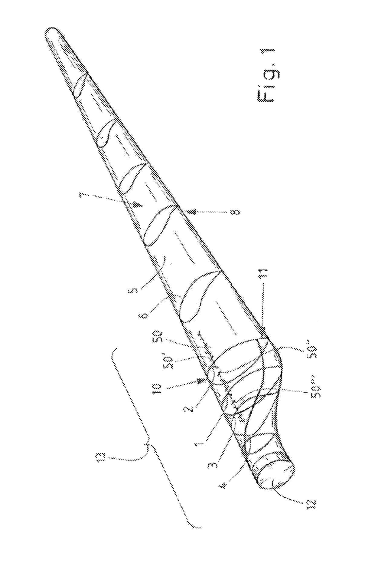
[0068]Shown schematically in FIG. 1 is a rotor blade 5 of a wind turbine, the latter not being represented, wherein some profiles 1-4 and 6 have already been drawn in.

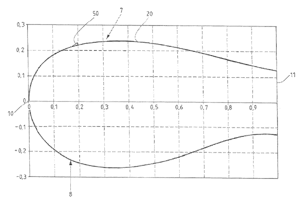
[0069]Profiles 1-4 are provided in a transition region 13 in the proximity of a rotor-blade root 12. The transition region 13 may be distinguished in that, for example, the trailing edge 11 no longer tapers, as in the case of the other profiles 6, but is blunt in form, for example becoming ever more blunt, the closer the profiles are to the rotor-blade root 12. To aid illustration, the leading edge 10 is also indicated, as well as an upper side, or suction side 7, and an underside, or pressure side 8. Of particular interest in the context of the invention are the profiles 1-4, which are located in the transition region 13, as well as additionally provided vortex generators 50, 50′, 50″ and 50′″. These profiles 1-4 are now to be explained in the following.

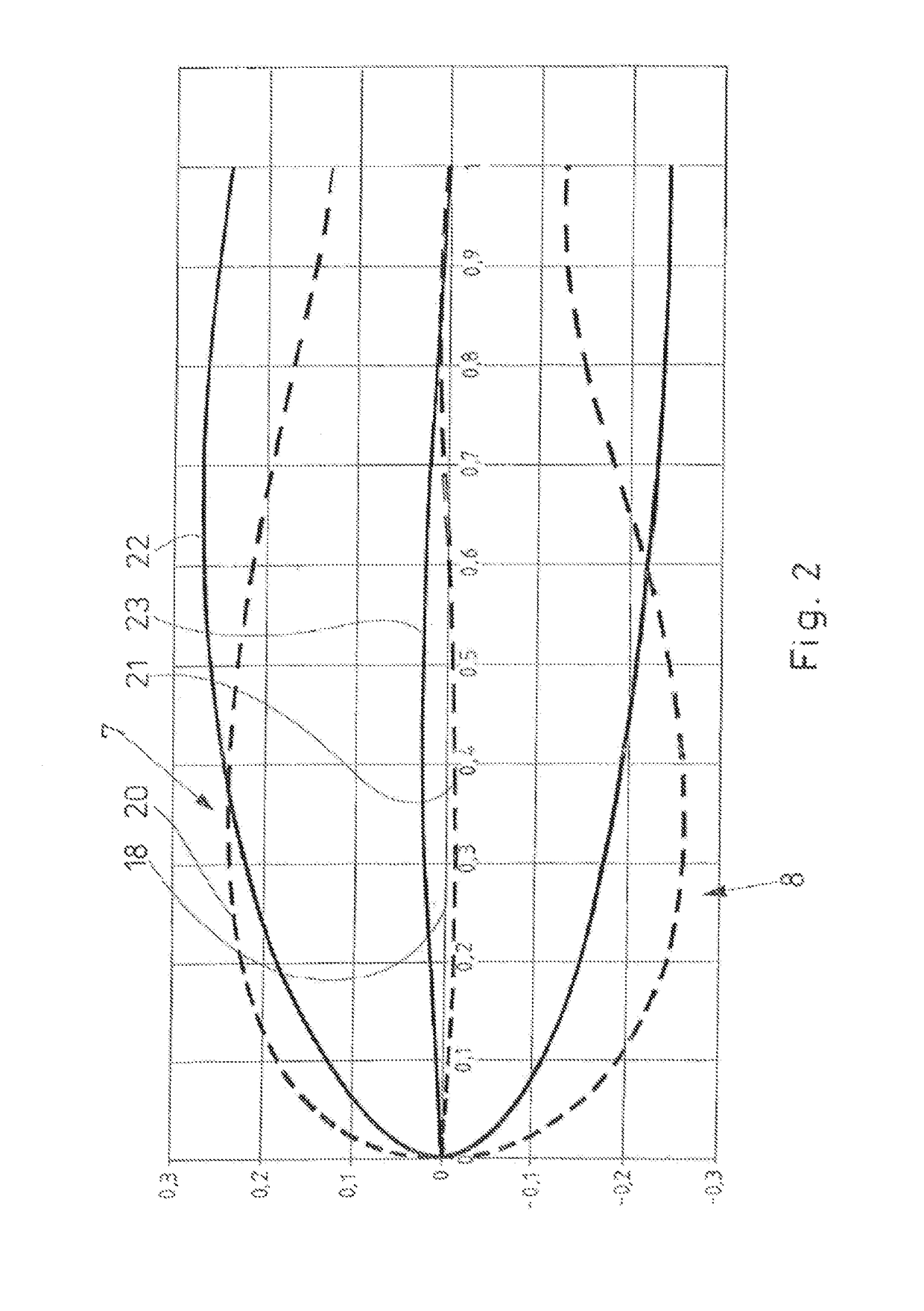
[0070]FIG. 2 shows a profile of a rotor blade 5 according to the ...


PUM


Abstract

A rotor blade (5) of a wind turbine, which has a profile (1-4) having an upper side (suction side) (7) and an underside (pressure side) (8). The profile (1-4) includes a camber line (21, 25) and a chord (18) between a leading edge (10) and a trailing edge (11) of the profile (1-4). The profile (1-4) has a relative profile thickness of more than 45%. At least one vortex generator (50, 50′, 50″, 50′″) is disposed, in the region of the profile (1-4), on the suction side (7) of the rotor blade (5). The profile (1-4) is provided with a blunt trailing edge. And, The thickness of the trailing edge is between 15% and 70% of the chord length.

Description

CROSS-REFERENCE TO RELATED APPLICATIONS[0001]This application is a continuation of International Application Number PCT / EP2014 / 000381, filed Feb. 12, 2014, and claims priority to DE 102013202666.8, filed Feb. 19, 2013.BACKGROUND OF INVENTION[0002]Field of Invention[0003]The invention relates to a rotor blade of a wind turbine, having a profile that has a suction side and a pressure side, wherein the profile comprises a camber line and a chord between a leading edge and a trailing edge of the profile, wherein the camber line extends at least portionally beneath the chord, in the direction of the pressure side, and wherein the profile has a relative profile thickness of more than 45%.[0004]Brief Description of Related Art[0005]Known from DE 10 2008 003 411 A1 are a rotor blade of a wind turbine and a corresponding family, or a plurality, of profiles. The airfoil profiles, or profiles, disclosed in this document have a blunt trailing edge, a substantially oval suction side and a substa...

Claims


Application Information

Patent Timeline
Patent Type & Authority Patents(United States)
IPC IPC(8): F03D1/06
CPCF03D1/0633F03D1/0683Y02E10/721F05B2240/32F05B2240/301Y02E10/72F05B2240/3062F03D1/0675
Inventor PETSCHE, MARCKORJAHN, CHRISTOPH MATTHIAS
Owner SIEMENS GAMESA RENEWABLE ENERGY SERVICE GMBH
Why Eureka
Try Eureka