Manufacturing method of display with lighting devices

a manufacturing method and technology of lighting devices, applied in semiconductor devices, semiconductor/solid-state device details, electrical apparatus, etc., can solve the problems of time-consuming and labor-intensive pick-and-place methods, and the difficulty of large-scale oled displays, and achieve the effect of quick and efficient assembly

Active Publication Date: 2018-04-03
INNOLUX CORP
View PDF1 Cites 2 Cited by
  • Summary
  • Abstract
  • Description
  • Claims
  • Application Information

AI Technical Summary

Benefits of technology

[0007]The disclosure is directed to a manufacturing method of display with lighting devices, and more particularly to an arrangement method of lighting devices of a display. According to the embodiment, at least one of the conductive pads of each lighting device includes a magnetic material. By applying an external magnetic field with magnetic force exerting on the lighting devices, a large number of the lighting devices can be arranged quickly and efficiently assembled to an array substrate of a display.

Problems solved by technology

Also, making a large size OLED display is considerably more challenging than LCD.
However, there are hundreds of thousands sub-pixels or couple million sub-pixels of a display, the pick-and-place method is very time-consuming, which is definitely not suitable for massive production.

Method used


Image

  • Manufacturing method of display with lighting devices
  • Manufacturing method of display with lighting devices
  • Manufacturing method of display with lighting devices

Examples


first embodiment

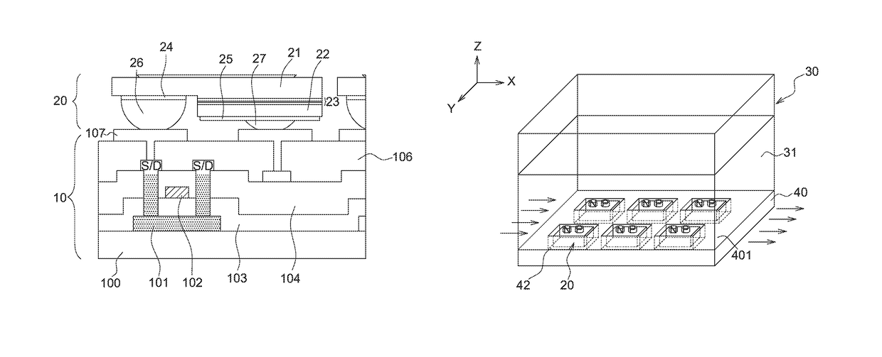
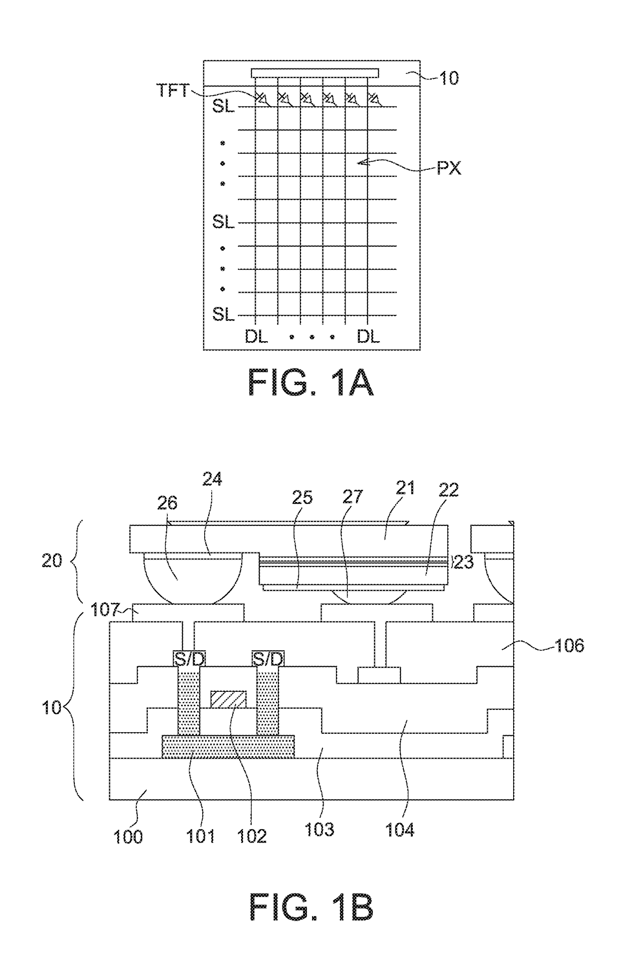
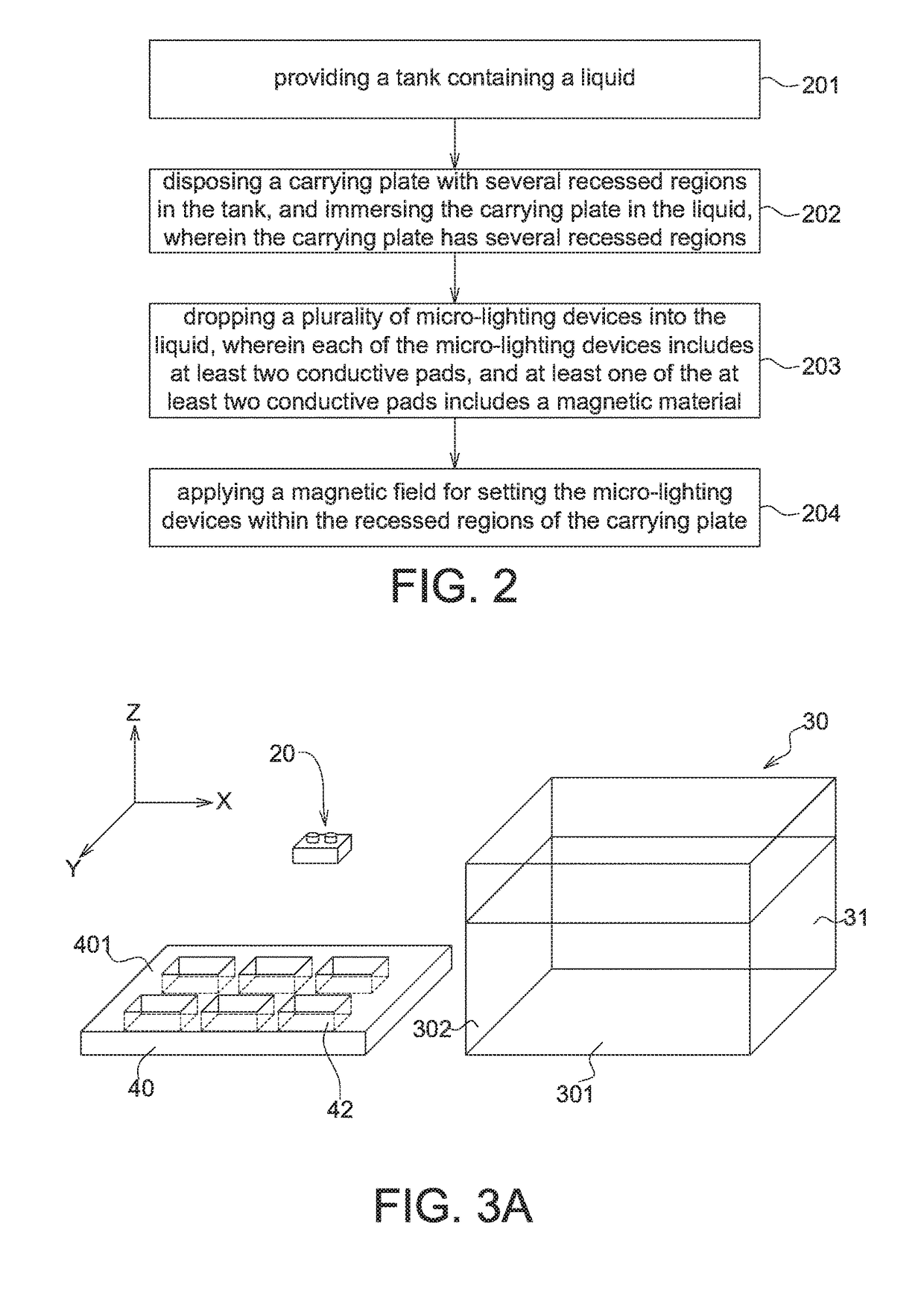
[0027]FIG. 3A-FIG. 3D illustrate an arrangement method of lighting devices of a display according to the first embodiment of the disclosure. First, a a tank 30 containing a liquid 31 and a carrying plate 40 having several recessed regions 42 are provided, as shown in FIG. 3A. Also, several lighting devices 20 such as micro-LED chips are provided. The recessed regions 42 of the carrying plate 40 can be positioned in accordance with the sub-pixel alignment of the display. For example, if the driving devices (ex: TFT) of the display in application are arranged as an array as shown in FIG. 1A, the recessed regions 42 can be arranged in an array and positioned correspondingly to the positions of the TFTs. Several portions of the top surface 401 of the carrying plate 40 can be recessed to form the recessed regions 42. In some embodiments, one recessed region 42 is positioned correspondingly to the position of one sub-pixel of the display. In some embodiments, two or more recessed regions ...

second embodiment

[0040]In the first embodiment, the carrying plate 40 can be disposed at the bottom surface of the tank 30 and in parallel with the horizontal level (i.e. XY-plane). However, the disclosure is not limited thereto. The carrying plate 40 disposed at the bottom surface of the tank 30 can be tilted to the horizontal level with a tilted angle θ. In the embodiment, the tilted angle θ between the carrying plate 40 and the horizontal level is in a range of 0 to 90 degrees (i.e. 0≤θ40 and the horizontal level is 0 degree in the first embodiment), or in a range of 0≤θ30 with a slanted bottom having an angle θ (<45 degrees) tilted to the XY-plane is demonstrated in the second embodiment, the disclosure is not limited thereto.

[0041]Also, the identical and / or similar elements of the second and first embodiments are designated with the same and / or similar reference numerals, and the details of the configurations and procedures of the identical components / steps are not redundantly described herein....

third embodiment

[0047]FIG. 6A-FIG. 6D illustrate an arrangement method of lighting devices of a display according to the third embodiment of the disclosure. The major difference between the first and third embodiments is the position of the carrying plate 40 in the tank 30. As shown in FIG. 6A, the carrying plate 40 is disposed at the sidewall 302 (vertical to the bottom 301 of the tank 30) of the tank 30, and the carrying plate 40 is vertical to the horizontal level. The upper surface of the carrying plate 40 is vertical to the horizontal level. Similarly, the carrying plate 40 of the third embodiment has several recessed regions 42, wherein the positions, shapes and sizes of the recessed regions 42 have been described above, and not redundantly repeated.

[0048]The lighting devices 20 are dropped in the liquid 31, and a magnetic field is applied for controlling the movement of the lighting devices 20 so as to set the lighting devices 20 within the recessed regions 42 of the carrying plate 40, as sh...


PUM


Abstract

A manufacturing method of display with lighting devices is disclosed, including providing a tank containing a liquid; disposing a carrying plate with several recessed regions in the tank, and the carrying plate being immersed in the liquid; dropping several lighting devices into the liquid, wherein each of the lighting devices includes two conductive pads, and one of the two conductive pads includes a magnetic material; applying a magnetic field for the lighting devices and the lighting devices will dispose within the recessed regions of the carrying plate; removing the carrying plate with the lighting devices out of the tank, and assembling the lighting devices to an array substrate.

Description

[0001]This application claims the benefit of a prior-filed provisional application Ser. No. 62 / 260,359, filed Nov. 27, 2015, and the benefit of People's Republic of China application Serial No. 201610521178.X, filed Jul. 5, 2016, the subject matters of which are incorporated herein by references.BACKGROUND[0002]Technical Field[0003]The disclosure relates in general to a manufacturing method of display with lighting devices, and more particularly to an arrangement method of lighting devices of a display.[0004]Description of the Related Art[0005]Electronic products with display panel, such as smart phones, tablets, notebooks, monitors, and TVs, have become indispensable necessities to modern people no matter in their work, study or entertainment. With a flourishing development of the portable electronic products, the consumers have higher expects on the functions, the specifications and the prices of the products. The development of next-generation display focuses on the energy saving...

Claims


Application Information

Patent Timeline
Patent Type & Authority Patents(United States)
IPC IPC(8): H01L27/12H01L21/683H01L23/00H01L25/075
CPCH01L27/1259H01L21/6835H01L24/05H01L2221/68368H01L2221/68309H01L2221/68313H01L2221/68354H01L25/0753
Inventor CHEN, BO-FENGHSIEH, TSAU-HUALIU, TUNG-KAI
Owner INNOLUX CORP
Why Eureka
Try Eureka