Automatic assembling equipment for bulb plastic core seat

An automatic assembly, plastic core technology, used in metal processing equipment, assembly machines, metal processing and other directions, can solve the problems of low degree of standardization, poor overall effect, low efficiency, etc., to achieve a high degree of standardization, fast and efficient assembly, and practical strong effect

Pending Publication Date: 2021-01-22
海盐县通元泽易机械厂 +1
View PDF0 Cites 3 Cited by
  • Summary
  • Abstract
  • Description
  • Claims
  • Application Information

AI Technical Summary

Problems solved by technology

Among them, the insertion operation and bending operation are often done manually, with low degree of standardization, low efficiency, and poor overall effect

Method used


Image

  • Automatic assembling equipment for bulb plastic core seat
  • Automatic assembling equipment for bulb plastic core seat
  • Automatic assembling equipment for bulb plastic core seat

Examples


Embodiment 1

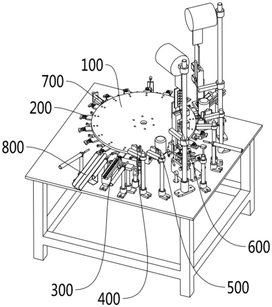
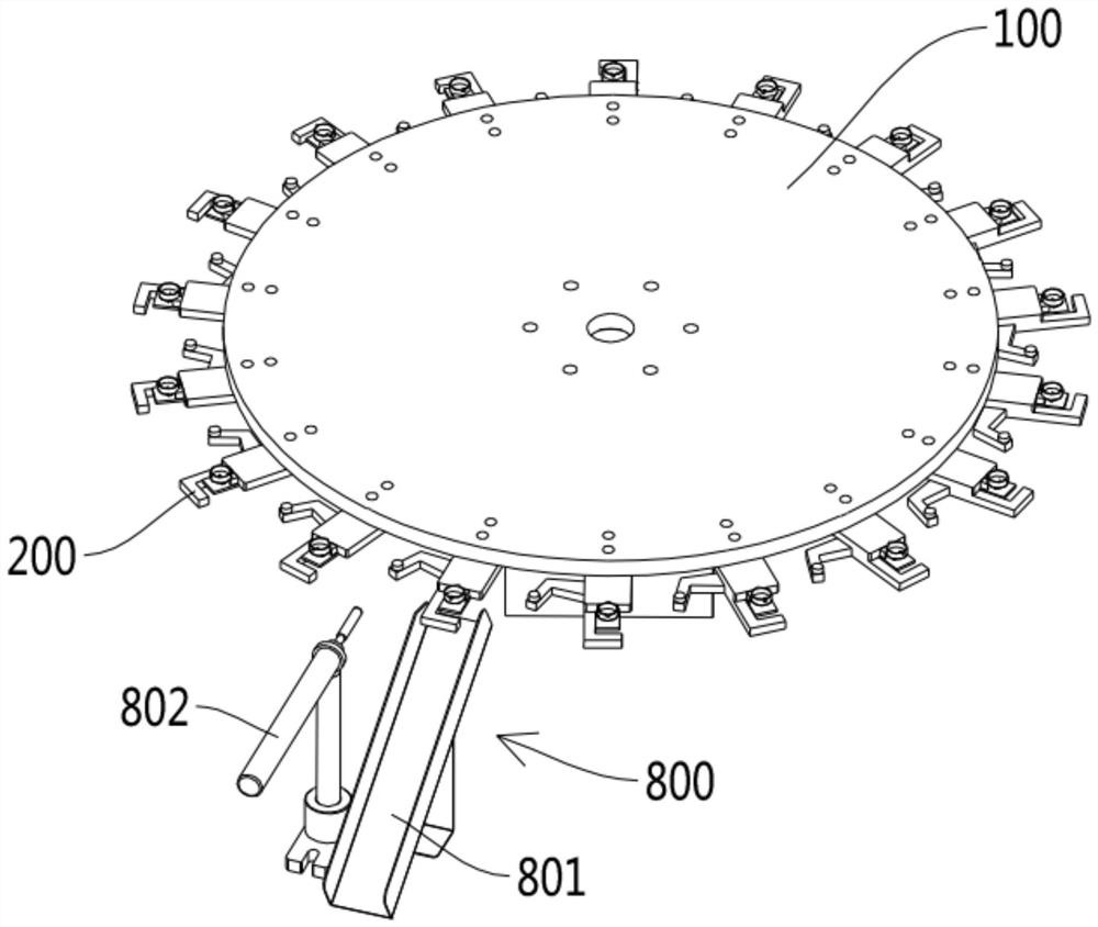
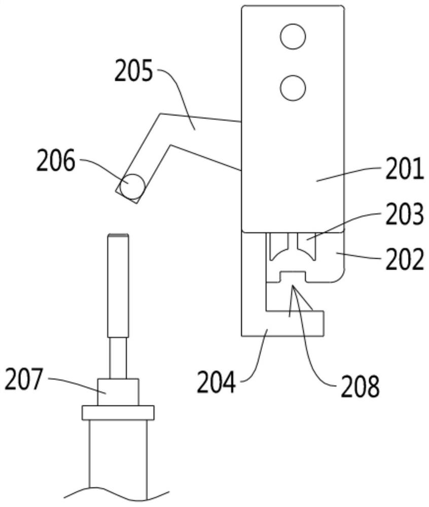
[0044] see Figures 1 to 22 As shown, the automatic assembly equipment for plastic bulb bases involved in this embodiment includes a turntable 100 controlled by a motor to rotate. The turntable 100 is provided with a number of loading clips 200, and the loading clips 200 include a clip seat 201 , the clamping seat 201 is provided with a loading plate 202 for holding the workpiece, the loading plate 202 is provided with a positioning block 203, the clamping seat 201 is rotatably connected with a clamping hook 204 for clamping the workpiece, and the clamping hook 204 is provided with The swing arm 205 is connected with a pulley 206 for rotation, and also includes a first push rod cylinder 207 that pushes the pulley 206. The rotating disk 100 is equipped with a feeding mechanism 300, a positioning mechanism 400, and a punching mechanism. 500 , an upper-line mechanism 600 , a line-folding mechanism 700 and a blanking mechanism 800 .

[0045] Further, the feeding mechanism 300 inc...


PUM


Abstract

The invention discloses automatic assembling equipment for a bulb plastic core seat. The automatic assembling equipment comprises a rotary disc controlled by a motor to rotate, a plurality of feedingclamps are arranged on the rotary disc, each feeding clamp comprises a clamping seat, a feeding plate for containing workpieces is arranged on each clamping seat, a positioning block is arranged on each feeding plate, a clamping hook for clamping the workpieces is rotationally connected to each clamping seat, a swing arm is arranged on each clamping hook, a pulley is rotationally connected to eachswing arm, each feeding clamp also comprises a first push rod air cylinder for pushing the corresponding pulley, and a feeding mechanism, a positioning mechanism, a punching mechanism, a wire feedingmechanism, a wire folding mechanism and a discharging mechanism are arranged outside the rotary disc in a matched mode. The automatic assembling equipment has the characteristics of being rapid in assembling, high in standardization degree and high in machining efficiency, and is complete in overall function and high in practicability.

Description

technical field [0001] The invention relates to the technical field of mechanical automation, more specifically, it relates to an automatic assembly equipment for a plastic core seat of a light bulb. Background technique [0002] Such as Figure 19 and Figure 20 As shown, it is a structural schematic diagram of an existing plastic core seat of a light bulb, which includes a plastic core seat 1000, a tailstock 1001 is provided at the bottom of the plastic core seat 1000, and a group of jacks 1002 are opened on the tailstock 1001 for plugging in After the hole 1002 is injection molded, it is easy to be blocked or the size does not meet the specification, and it is inconvenient to punch holes after processing. [0003] After the jack hole 1002 is drilled, the first metal wire 1003 and the second metal wire 1004 of different lengths (such as Figure 21 As shown), the first metal wire 1003 and the second metal wire 1004 need to be bent away from the end of the tailstock 1001, ...

Claims


Application Information

Patent Timeline
Patent Type & Authority Applications(China)
IPC IPC(8): B23P21/00B23P19/027B23P19/00
CPCB23P19/001B23P19/002B23P19/027B23P21/006
Inventor 冯泽易叶建新
Owner 海盐县通元泽易机械厂
Why Eureka
Try Eureka